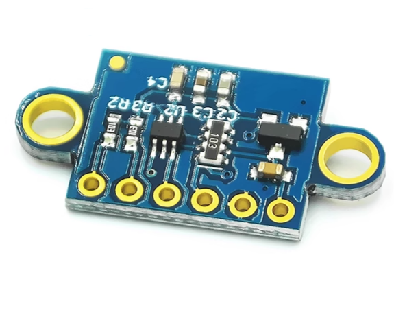
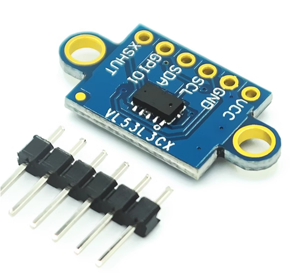
VL53L3CX Laser Ranging Sensor Module – 3m Multi-Target Detection with 25×13.3mm Optical Cover

SKU: FA3021-15
Sensor IC

STMicroelectronics VL53L3CX

Ranging Range

Up to 3m (up to 5m under good conditions)

Laser Wavelength

940nm (invisible infrared VCSEL)

Field of View (FoV)

25° (typical)

Communication Interface

I²C (up to 1MHz)

Supply Voltage

2.6V – 3.5V

Package Size

4.4×2.4×1mm (sensor); optical cover 25×13.3mm

Power Consumption

6µA hardware standby; <1mW ranging

The VL53L3CX Laser Ranging Sensor Module is an advanced, high-precision Time-of-Flight (ToF) distance sensor built on STMicroelectronics’ third-generation FlightSense™ technology. Compared to the previous VL53L0X and VL53L1X, the VL53L3CX’s core advantage is its multi-target detection capability — it can simultaneously detect multiple objects within its field of view (FoV) and output distance data for each object, not just the nearest one.

The module uses a 940nm invisible laser (VCSEL) emitter and a single-photon avalanche diode (SPAD) array receiver, combined with ST’s patented histogram algorithm, to achieve the following breakthrough features:

  • Multi-target detection — Simultaneously detects multiple objects (up to 4) within the field of view, outputting distance information for each target, enabling robots to “understand” scene depth rather than merely sensing the nearest obstacle.

  • Cover glass crosstalk immunity — The patented algorithm makes the sensor immune to crosstalk caused by cover glass at distances above 80cm, meaning accurate long-range ranging performance is maintained even when the sensor is mounted behind a glass or acrylic panel.

  • Dynamic smudge compensation — Automatically compensates for signal attenuation caused by fingerprints, dust, and other smudges on the cover glass, maintaining stable ranging accuracy over time.

The module’s optical cover measures 25×13.3mm, a compact design that allows it to be easily embedded into various device enclosures while protecting the internal precision optical components. The sensor itself has a package size of only 4.4×2.4×1mm and is pin-compatible with the VL53L0X and VL53L1X, facilitating upgrades and replacements in existing designs.

The VL53L3CX has a ranging range of up to 3m (up to 5m under good conditions), a field of view of 25°, and ranging results are unaffected by target color or reflectivity. The module communicates via an I²C interface (up to 1MHz) and supports interrupt and Xshutdown reset pins to optimize power consumption.

Important Note: The VL53L3CX API has high memory and processing requirements for the host processor (requiring a 32-bit MCU such as STM32). 8-bit Arduinos struggle to run the full multi-target detection algorithm. For resource-constrained applications, the VL53L1X or VL53L0X is recommended.

The module is widely used in service robots, vacuum cleaners, smart buildings, smart lighting, IoT devices, laser autofocus, and other scenarios.

Features

  • Third-generation FlightSense™ technology — ST’s latest ToF sensor with exceptional performance

  • Multi-target detection capability — Simultaneously detects up to 4 objects and their distances within the field of view

  • 3m ranging range — Up to 5m under good conditions

  • 940nm invisible laser — Class 1 eye-safe VCSEL emitter

  • Cover glass crosstalk immunity — Immune to cover glass crosstalk above 80cm

  • Dynamic smudge compensation — Automatically compensates for fingerprints and dust

  • 25° field of view — Typical full field of view

  • I²C interface — Up to 1MHz communication rate

  • Optical cover dimensions — 25×13.3mm for easy integration

  • Pin compatible — Compatible with VL53L0X / VL53L1X pins

Technical Specifications 

# Parameter Specification
1 Sensor IC STMicroelectronics VL53L3CX
2 Ranging Range Up to 3m (up to 5m under good conditions)
3 Laser Wavelength 940nm (invisible infrared VCSEL)
4 Field of View (FoV) 25° (typical)
5 Communication Interface I²C (up to 1MHz)
6 Supply Voltage 2.6V – 3.5V
7 Package Size 4.4×2.4×1mm (sensor); optical cover 25×13.3mm
8 Power Consumption 6µA hardware standby; <1mW ranging

Usage

Getting Started

  1. Connect power — Supply 2.6V to 3.5V to the VDD pin and GND to ground.

  2. Connect I²C — Connect SDA and SCL to your host MCU’s I²C bus (4.7KΩ pull-up resistors required).

  3. Connect control pins — Connect the XSHUT pin to an MCU GPIO for reset control, and the INT pin for interrupt notification.

  4. Install the driver library — Use ST’s official VL53L3CX Arduino library (STM32duino) or the STSW-IMG015 bare driver. The library requires a 32-bit MCU (such as STM32 Nucleo).

  5. Calibrate (recommended) — Perform offset calibration and crosstalk calibration for best accuracy. If using an optical cover, cover glass crosstalk calibration is required.

  6. Read data — After initializing the sensor, obtain multi-target ranging data via the API, including the distance and status of each target.

Pin Connections (Typical)

Pin Function
VDD Power (2.6V–3.5V)
GND Ground
SDA I²C Data
SCL I²C Clock
XSHUT Reset (active low)
INT Interrupt output

Typical Applications

  • Service robots and vacuum cleaners — Wall tracking and fast obstacle detection

  • Smart buildings and lighting — User detection to wake devices

  • IoT devices — User and object detection

  • Laser autofocus — Camera focus assistance

  • Video focus tracking — Camera tracking assistance

Notes for Business Buyers

  • Multi-target detection advantage — A single sensor can obtain scene depth information, reducing the number of sensors required.

  • Cover glass crosstalk immunity — Can be hidden behind glass/acrylic panels, suitable for product appearance design.

  • 32-bit MCU requirement — Must be used with a 32-bit processor such as STM32; 8-bit Arduinos are not suitable.

  • Suitable for bulk purchasing — Ideal for robot manufacturers, smart home product developers, and educational institutions.

Q: What is the difference between the VL53L3CX and VL53L0X?

The VL53L3CX is ST’s third-generation ToF sensor, supporting multi-target detection (simultaneously detecting multiple objects), with cover glass crosstalk immunity and dynamic smudge compensation. The VL53L0X can only detect a single distance and requires fewer memory resources.

Q: What is multi-target detection?

The VL53L3CX uses a histogram algorithm to detect multiple objects (up to 4) within its field of view and outputs the distance of each object. This enables robots to distinguish foreground from background objects.

Q: What is the module's ranging range?

The official specification states up to 3m. Pololu notes that after ST updated the API, it can actually reach 5m.

Q: What is the optical cover size?

The module’s optical cover measures 25×13.3mm, making it easy to embed into device enclosures.

Q: Can it be driven by an 8-bit Arduino?

Not recommended. The VL53L3CX API requires significant memory and processing power. Pololu’s testing indicates it cannot run on typical 8-bit Arduinos. A 32-bit MCU (such as STM32) is recommended.

Q: How do I calibrate the sensor?

Offset calibration and RefSpad calibration are required. If using an optical cover, crosstalk calibration is also required. ST provides GUI tools and API support for the calibration process.

Q: What is the supply voltage?

The sensor supply voltage range is 2.6V to 3.5V.

Q: What is the I²C address?

The default I²C address is 0x29 (7-bit).

Q: Is it pin-compatible with the VL53L0X?

Yes, the VL53L3CX is pin-compatible with the VL53L0X and VL53L1X, facilitating upgrades and replacements.

Q: Can I purchase in bulk for product development?

Yes. This module is suitable for bulk purchasing by robot manufacturers, smart home product developers, and educational institutions.