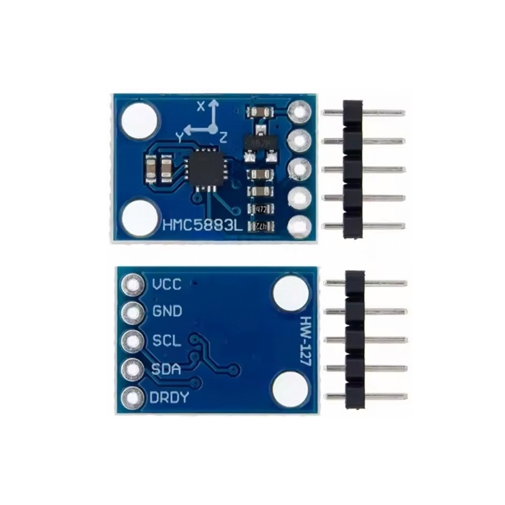
The GY-273 HMC5883P 3-Axis Magnetometer Compass Module is a compact, high-sensitivity magnetic field sensor designed for digital compass, orientation detection, and navigation applications. Built around the HMC5883P chip, this module is a modernized successor to the widely used HMC5883L, offering improved availability and performance for demanding projects.
At the heart of the module is the HMC5883P, a 3-axis magnetoresistive sensor with 12-bit ADC resolution that measures magnetic fields across the X, Y, and Z axes. The sensor utilizes Honeywell’s Anisotropic Magnetoresistive (AMR) technology, which provides advantages over other magnetic sensor technologies, including precision in-axis sensitivity and low cross-axis sensitivity. With a measurement range of ±1.3 to ±8 Gauss, it is designed to measure both the direction and magnitude of Earth’s magnetic field, from milli-gauss to 8 gauss.
The module includes onboard voltage regulation and level shifting, allowing it to operate from 3V to 5V supplies — making it directly compatible with both 3.3V and 5V microcontrollers like Arduino Uno, ESP32, and STM32. The I2C interface operates at up to 400 kHz and the module includes 4.7kΩ pull-up resistors for reliable communication.
The GY-273 module breaks out the HMC5883P chip onto a compact PCB measuring approximately 18 × 13 mm, with a standard 2.54mm pin header for breadboard and jumper wire connections. The pinout includes VCC, GND, SCL, SDA, and DRDY (data-ready interrupt, optional).
Important Note: The HMC5883P uses a different I2C address than the older HMC5883L. The HMC5883L uses address 0x1E, while the HMC5883P typically uses a different address. Always verify the correct address for your specific module revision. Libraries may require adjustment for the HMC5883P variant.
Whether you are building a digital compass, a robot with navigation capabilities, a drone flight controller, or a handheld GPS logger, the GY-273 HMC5883P provides a reliable, cost-effective foundation for magnetic sensing. It is suitable for individual makers, students, and businesses purchasing in bulk for product development or educational programs.
Features
-
HMC5883P 3-axis magnetometer — High-resolution magnetic field sensing in X, Y, and Z axes
-
12-bit ADC resolution — Enables 1° to 2° compass heading accuracy
-
AMR technology — Anisotropic Magnetoresistive sensors provide precision in-axis sensitivity
-
Wide measurement range — ±1.3 to ±8 Gauss
-
I2C digital interface — Simple connection with only two data lines, up to 400 kHz
-
Wide supply voltage — 3V to 5V operation with onboard regulation and level shifting
-
Data-ready (DRDY) pin — Optional interrupt for efficient data reading
-
Compact module form factor — Approx. 18 × 13 mm with standard pin header
-
Onboard pull-up resistors — 4.7kΩ for reliable I2C communication
-
Wide library support — Compatible with HMC5883L Arduino libraries
Technical Specifications
Usage
Getting Started
-
Connect power — Supply 3V to 5V to the VCC pin and GND to ground.
-
Connect I2C lines — Connect SDA to your microcontroller’s I2C data line and SCL to the I2C clock line.
-
Arduino Uno: SDA → A4, SCL → A5
-
ESP32: SDA → GPIO21, SCL → GPIO22 (default)
-
ESP8266: SDA → D2, SCL → D1
-
Install the library — Install the HMC5883L_Simple library or Adafruit HMC5883 Unified library through the Arduino Library Manager.
-
Verify communication — Run an I2C scanner sketch to confirm the module’s address. Note that HMC5883P may use a different address than the HMC5883L’s 0x1E.
-
Upload a test sketch — Use a basic example to read magnetic field values on X, Y, and Z axes. Calculate heading using atan2(Y, X).
Pin Connections
Calibration Notes
For accurate compass heading, the HMC5883P should be calibrated to compensate for hard-iron and soft-iron magnetic distortions. The common approach involves rotating the sensor through all orientations and recording min/max values for each axis, then applying offset and scale corrections in your code. The HMC5883L_Simple library includes built-in support for magnetic declination adjustment.
Typical Applications
-
Digital compass — Determine direction relative to magnetic north
-
Robotics navigation — Provide heading reference for mobile robots
-
Drone flight controllers — Orientation reference for stabilization
-
Handheld GPS loggers — Combine with GPS for bearing calculations
-
Location-based services — Position and direction sensing
-
Educational projects — Teaching magnetic sensing and I2C communication
Notes for Business Buyers
-
HMC5883L successor — The HMC5883P is the updated variant as HMC5883L becomes less available.
-
Wide voltage compatibility — Onboard regulation simplifies integration with 3.3V and 5V systems.
-
Proven technology — AMR magnetoresistive sensing is widely adopted and well-documented.
-
Suitable for bulk purchasing — Ideal for product development, educational kits, and commercial deployments.
Q: What is the GY-273 HMC5883P module used for?
It is a 3-axis magnetometer for digital compass, orientation detection, magnetic field measurement, and navigation applications in Arduino and microcontroller projects.
Q: Is the HMC5883P compatible with HMC5883L libraries?
The HMC5883P may use a different I2C address than the HMC5883L (0x1E). Verify the address for your specific module and adjust your code if necessary. Some libraries may work with modifications.
Q: What is the I2C address of this module?
The address depends on the specific HMC5883P variant. The older HMC5883L uses 0x1E. Run an I2C scanner to confirm the address for your module.
Q: What is the measurement range?
The module supports ±1.3 to ±8 Gauss measurement range.
Q: What voltage does the module require?
It operates from 3V to 5V thanks to its onboard voltage regulator and level shifting.
Q: How do I calculate compass heading?
Use the formula heading = atan2(Y, X) where Y and X are the magnetic field readings. Convert the result to degrees and adjust for declination if needed.
Q: Does the module require calibration?
Yes. For accurate compass heading, the HMC5883P should be calibrated to compensate for magnetic distortions in your environment.
Q: Can I use this module with an ESP32?
Yes. Connect SDA to GPIO21 and SCL to GPIO22 (default I2C pins), and use an HMC5883L-compatible library.
Q: What is the difference between HMC5883P and HMC5883L?
The HMC5883P is a newer variant that offers improved availability. They share similar functionality, but may have different I2C addresses and register configurations. Always verify compatibility with your chosen library.
Q: Can I purchase in bulk for a product development project?
Yes. This module is suitable for both individual users and business purchasing, including product development, educational programs, and commercial deployments.