ESP-12 WiFi Module – Compact, Low-Power Wireless Solution for IoT Projects

SKU: FA2069-3
Chipset

Espressif ESP8266EX

Processor

32-bit Tensilica L106 RISC @ 80 MHz (160 MHz max)

Flash Memory

4 MB SPI Flash

Wireless Standard

IEEE 802.11 b/g/n

Operating Voltage

3.0V – 3.6V (3.3V typical)

Operating Current

80mA average; <10µA deep sleep

GPIO Count

20 pins

Dimensions

16 × 24 × 3 mm

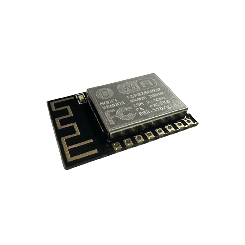
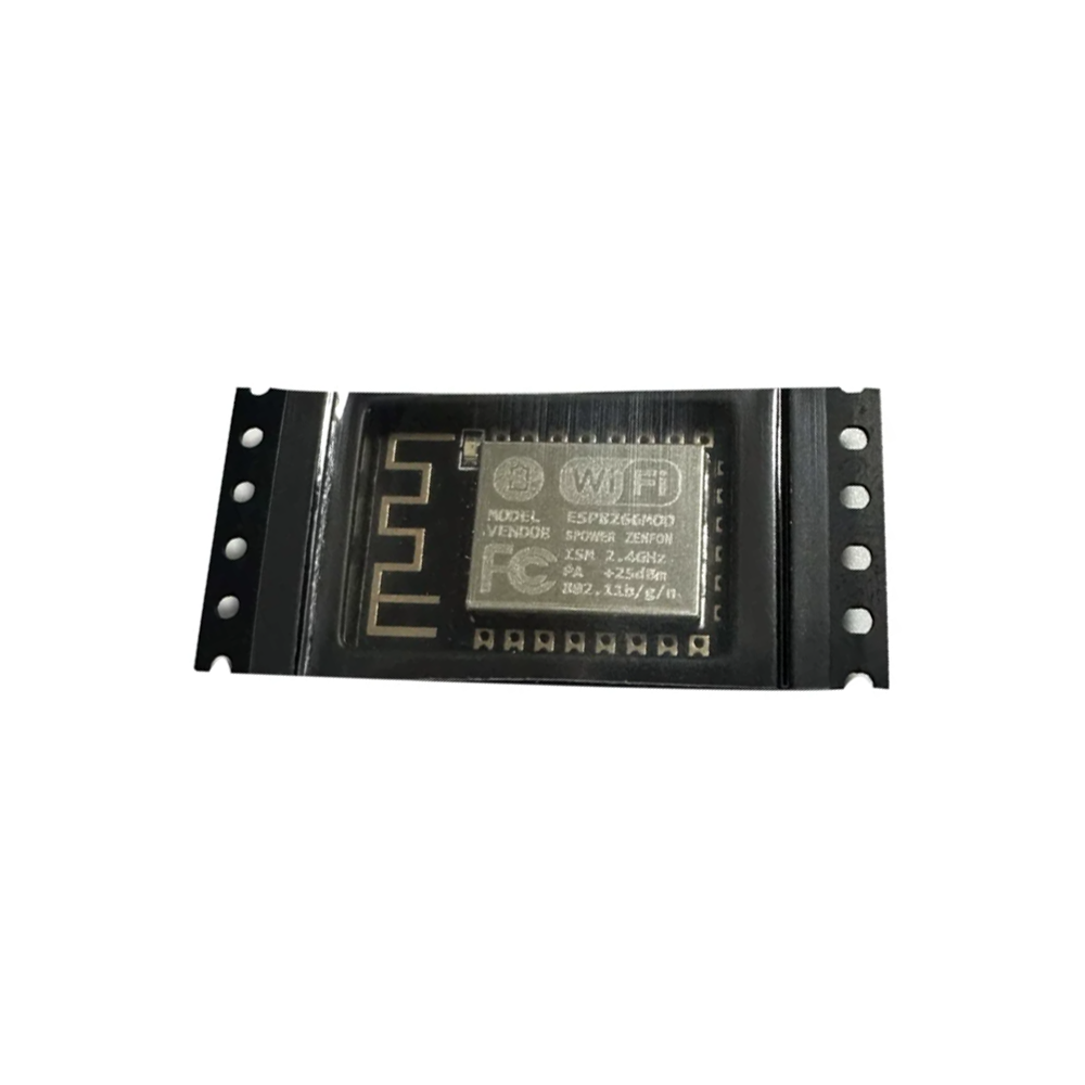
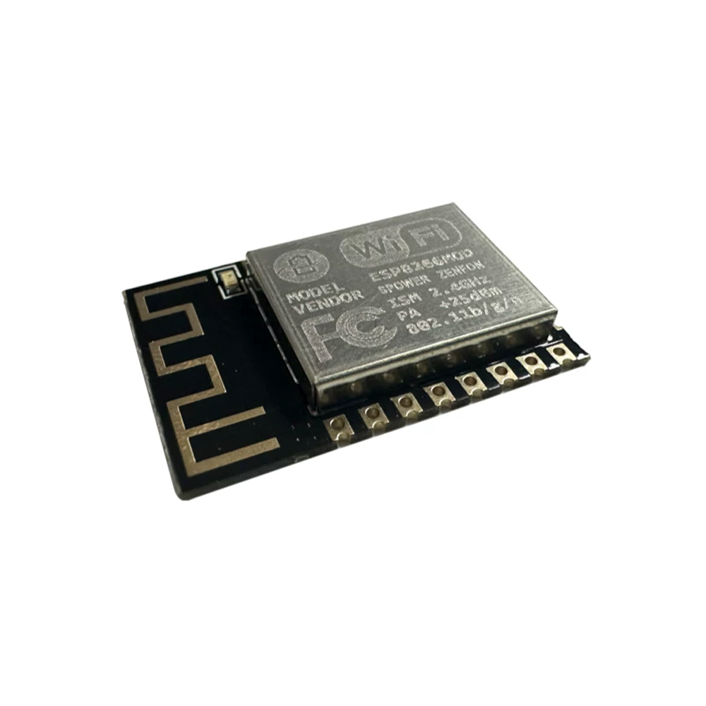
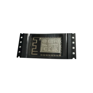
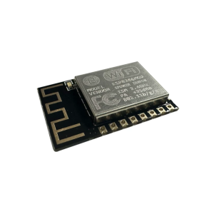
The ESP-12 WiFi Module is a compact, low-power wireless transceiver built around the Espressif ESP8266EX chipset, designed to add WiFi connectivity to microcontroller projects, IoT devices, and embedded systems. As one of the most widely adopted WiFi modules in the maker and professional communities, the ESP-12 offers a proven combination of performance, affordability, and extensive ecosystem support.

At its core is the ESP8266EX, a highly integrated 32-bit Tensilica L106 RISC processor running at up to 80 MHz (overclockable to 160 MHz). The chip integrates 4 MB of SPI flash, 80 KB DRAM, and 32 KB instruction RAM, providing sufficient resources for WiFi protocol stacks and user applications. The module supports IEEE 802.11 b/g/n wireless standards with WiFi Direct (P2P) , soft-AP , and station mode capabilities.

The ESP-12 features a complete and self-contained WiFi networking solution, allowing it to either host an application or offload all WiFi networking functions from another application processor. When the ESP-12 is used as a WiFi adapter, it can be connected to any microcontroller via UART (TX/RX) , and the onboard AT command firmware enables simple configuration and data transmission.

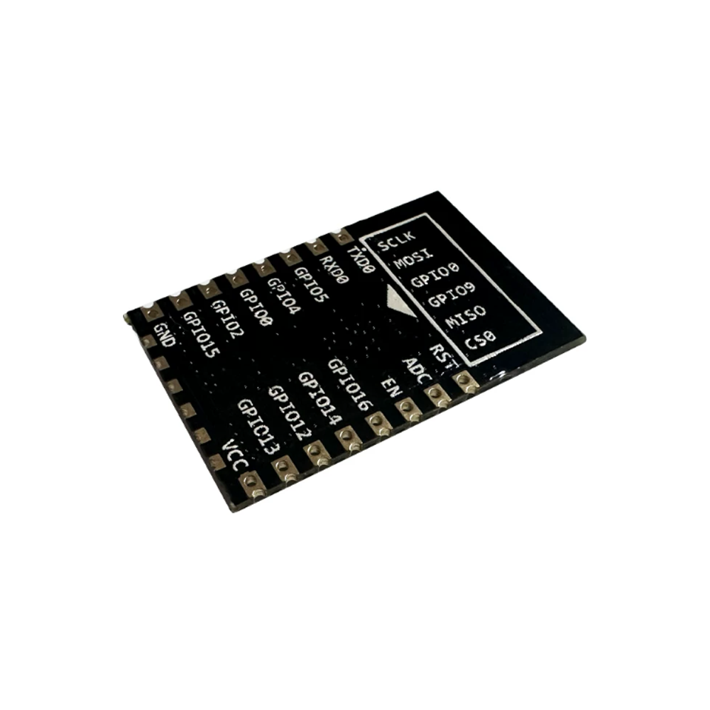
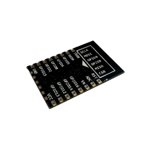
With 20 available GPIO pins, the ESP-12 exposes a rich set of interfaces including UART, SPI, I2C, PWM, and ADC . The module also supports over-the-air (OTA) firmware upgrades and serial bootloading , making it easy to update deployed devices without physical access.

The module operates from 3.0V to 3.6V (3.3V typical) and consumes an average of 80mA during normal operation, dropping to less than 10µA in deep sleep mode. This makes it suitable for battery-powered IoT applications. The compact 16 × 24 × 3 mm form factor and castellated edge pads allow for easy soldering directly onto PCBs or use with standard 2.54mm pin headers.

The ESP-12 has achieved FCC, CE, and TELEC certifications , ensuring compliance for international markets. It is supported by Arduino IDE, ESP-IDF, and MicroPython , with extensive community libraries and examples available.

Whether you are building a smart home device, a wireless sensor node, or a cloud-connected IoT product, the ESP-12 provides a practical, cost-effective foundation for WiFi connectivity. It is suitable for individual makers, students, and businesses purchasing in bulk for product development or educational programs.


Features

  • ESP8266EX chipset — 32-bit Tensilica L106 RISC processor at up to 80 MHz (160 MHz overclockable)

  • IEEE 802.11 b/g/n WiFi — Supports station mode, soft-AP, and WiFi Direct (P2P)

  • 4 MB SPI Flash — Ample storage for firmware and data

  • Complete WiFi networking solution — Can host applications or offload WiFi functions from another MCU

  • AT command firmware — Simple UART-based configuration and data transmission

  • 20 GPIO pins — Exposed for UART, SPI, I2C, PWM, and ADC

  • OTA firmware upgrades — Update deployed devices without physical access

  • Compact form factor — 16 × 24 × 3 mm with castellated edge pads for direct PCB soldering

  • Ultra-low power consumption — Less than 10µA in deep sleep mode

  • Wide development support — Arduino IDE, ESP-IDF, and MicroPython compatible


Technical Specifications

# Parameter Specification
1 Chipset Espressif ESP8266EX
2 Processor 32-bit Tensilica L106 RISC @ 80 MHz (160 MHz max)
3 Flash Memory 4 MB SPI Flash
4 Wireless Standard IEEE 802.11 b/g/n
5 Operating Voltage 3.0V – 3.6V (3.3V typical)
6 Operating Current 80mA average; <10µA deep sleep
7 GPIO Count 20 pins
8 Dimensions 16 × 24 × 3 mm

Usage

Getting Started

  1. Power the module — Supply 3.3V to the VCC pin and GND to ground. Important: The ESP-12 is not 5V tolerant. Using 5V will damage the module. Use a dedicated 3.3V regulator capable of supplying at least 300mA.

  2. Connect UART — Cross-connect the module‘s TX and RX to your USB-to-TTL adapter’s RX and TX. The default baud rate for AT firmware is 115200.

  3. Enter programming mode — For flashing new firmware, connect GPIO0 to GND and GPIO15 to GND, then reset the module. For normal operation, disconnect GPIO0 from GND.

  4. Test communication — Open a serial terminal at 115200, 8N1. Send AT; the module should respond with OK.

  5. Configure WiFi — Use AT commands to set the module as a station (AT+CWMODE=1), connect to an access point (AT+CWJAP="SSID","password"), and establish TCP/UDP connections.

Essential AT Commands

Command Function
AT Test communication
AT+CWMODE=1 Set station mode
AT+CWMODE=2 Set soft-AP mode
AT+CWMODE=3 Set station + soft-AP mode
AT+CWJAP="SSID","PASS" Connect to WiFi network
AT+CIFSR Get IP address
AT+CIPSTART="TCP","IP",PORT Establish TCP connection
AT+CIPSEND=length Send data
AT+RST Restart module
AT+GMR Check firmware version

Typical Applications

  • Smart home devices — Connected switches, sensors, and controllers

  • Wireless sensor nodes — Remote monitoring and data collection

  • IoT gateways — Bridge local devices to cloud platforms

  • Home automation — Control appliances and lighting via WiFi

  • Industrial monitoring — Equipment status and data transmission

  • Wearable devices — Compact WiFi connectivity for portable electronics

Notes for Business Buyers

  • Proven platform — ESP8266 is one of the most widely adopted WiFi chips with extensive documentation and community support.

  • Cost-effective — Low unit cost makes it practical for volume production and educational programs.

  • Certified — FCC, CE, and TELEC certified for international markets.

  • Suitable for bulk purchasing — Ideal for IoT product development, educational kits, and commercial deployments.

Q: What is the ESP-12 WiFi Module used for?

It is a compact WiFi transceiver for IoT projects, smart home devices, wireless sensor nodes, and any application requiring WiFi connectivity.

Q: Is the ESP-12 5V tolerant?

No. The ESP-12 operates at 3.3V logic and is not 5V tolerant. Applying 5V to any pin will damage the module. Use a 3.3V regulator and level shifters if interfacing with 5V devices.

Q: What is the difference between ESP-12, ESP-12E, and ESP-12F?

The ESP-12E and ESP-12F are improved versions of the original ESP-12, with better antenna design and additional GPIO pins. The ESP-12F is the most recent and recommended version.

Q: How do I program the ESP-12?

You can program it using Arduino IDE, ESP-IDF, or MicroPython. For initial flashing, connect GPIO0 to GND, GPIO15 to GND, and use a USB-to-TTL adapter at 3.3V logic.

Q: What is the default baud rate for AT firmware?

The default baud rate is 115200 for most AT firmware versions. Some older versions may use 9600.

Q: How much current does the module require?

The module draws an average of 80mA during normal operation and can peak at 300mA during WiFi transmission. Use a power supply capable of at least 300mA.

Q: Does the ESP-12 support OTA updates?

Yes. The ESP-12 supports over-the-air (OTA) firmware upgrades, allowing you to update deployed devices without physical access.

Q: What is the deep sleep current?

The deep sleep current is less than 10µA, making it suitable for battery-powered applications.

Q: Can I use the ESP-12 as a WiFi adapter for another microcontroller?

Yes. With AT command firmware, the ESP-12 can function as a WiFi adapter for any microcontroller via UART, handling all WiFi networking functions.

Q: Can I purchase in bulk for a product development project?

Yes. The ESP-12 is suitable for both individual users and business purchasing, including IoT product development, educational programs, and commercial deployments.