Product Overview
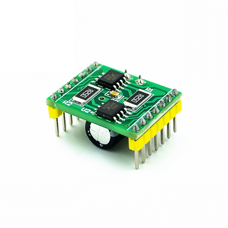
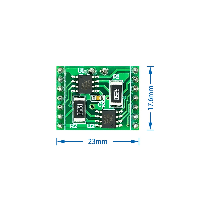
The A4950 Dual-Channel Brushed DC Motor Driver Module is a high-performance, high-voltage motor driver board designed to control two brushed DC motors independently or one 4-wire bipolar stepper motor . Based on the Allegro MicroSystems A4950 full-bridge DMOS driver IC, this module supports an impressive operating voltage range of 8V to 40V with a continuous output current of 2A per channel and peak current capability of up to 3.5A .
This module stands out as a superior alternative to popular drivers like the TB6612 and L298N, particularly in demanding applications requiring higher voltage and robust protection features. The TB6612 typically operates only up to 13.5V with 1.2A continuous current, while the L298N, despite its 2A rating, suffers from high on-resistance (~2Ω) leading to significant heat generation . The A4950, with its low RDS(on) MOSFET design and comprehensive integrated protection, delivers cleaner, more efficient power and is better suited for 12V, 24V, and even 36V industrial systems .
In industrial automation, CNC machinery, robotics, and smart home devices, the A4950 is engineered for demanding scenarios requiring precise PWM (Pulse Width Modulation) speed control. It features a suite of onboard protection circuits including overcurrent protection (OCP), thermal shutdown with hysteresis, undervoltage lockout, and motor lead short-to-ground (battery) protection, ensuring unparalleled system reliability .
This driver module simplifies control with a standard 6-pin interface: VCC, GND, DIR (Direction), and EN (Enable/PWM). It is widely used for actuating conveyor belts, CNC spindle motors, automated blinds, and battery-powered electric vehicles, where high efficiency and thermal management are critical .
Key Features
-
Wide Operating Voltage: Supports 8V to 40V DC, compatible with 12V, 24V, and 36V industrial power systems .
-
High Current Output: Delivers 2A continuous current per channel with 3.5A peak capacity, providing high torque for demanding loads .
-
Low RDS(on) Resistance: Features low internal resistance (approx. 0.45Ω) for high efficiency and minimal heat generation .
-
Independent Motor Control: Two independent H-bridges allow simultaneous, bidirectional speed control of two DC motors .
-
Simple PWM Control Interface: Standard 4-pin control logic (DIR and PWM per motor) allows easy connection to Arduino, ESP32, and STM32 .
-
Comprehensive Integrated Protection: Includes Overcurrent Protection (OCP), Thermal Shutdown (TSD), and Undervoltage Lockout (UVLO) .
-
Synchronous Rectification: Built-in synchronous rectification improves efficiency and reduces power loss during PWM operation .
-
Compact Form Factor: Utilizes a low-profile 8-pin SOICN package, making it suitable for space-constrained designs .
Technical Specifications
Pinout & Interface Guide
The typical A4950 Dual Module pinout is arranged for standard control. Note: Check your specific module labeling.
Control Pins
Motor Terminals
-
OUT1A, OUT2A: Connect to first DC motor.
-
OUT1B, OUT2B: Connect to second DC motor.
Control Logic Table (Per Channel)
Usage Guide
Typical Wiring for Industrial Control (Arduino/ESP32)
Setting up the A4950 requires proper power separation. High-voltage spikes can cause microcontroller resets if the circuit is not properly decoupled .
-
Power Supply: Connect a 12V-24V power supply to the VM terminal. Connect a clean 5V supply to the VCC terminal (if the board does not have a built-in regulator). Some modules use VM to power the logic via an internal regulator; verify your board layout .
-
Connect Motors: Connect two DC motors to the respective output terminal blocks.
-
Control Signals: Connect EN1, DIR1, EN2, DIR2 to 6 digital pins on your microcontroller (e.g., D5, D6, D9, D10).
-
Critical Ground: Ensure the GND of the driver board is solidly connected to the GND of your microcontroller. Without this, the control signals will not function .
Basic Arduino Example
int EN1 = 5;
int DIR1 = 6;
int EN2 = 9;
int DIR2 = 10;
void setup() {
pinMode(EN1, OUTPUT);
pinMode(DIR1, OUTPUT);
pinMode(EN2, OUTPUT);
pinMode(DIR2, OUTPUT);
}
void loop() {
digitalWrite(DIR1, HIGH);
analogWrite(EN1, 127);
digitalWrite(DIR2, LOW);
analogWrite(EN2, 191);
delay(3000);
digitalWrite(EN1, LOW);
digitalWrite(EN2, LOW);
delay(2000);
}
Q: Why choose the A4950 over the popular TB6612?
The A4950 is the superior choice for high-voltage applications. The TB6612 is limited to 13.5V, whereas the A4950 operates efficiently up to 40V, making it necessary for 24V or 36V industrial systems . Additionally, the A4950 offers robust overcurrent protection (OCP) and internal synchronous rectification, enhancing reliability and efficiency, while the TB6612 relies primarily on thermal shutdown .
Q: What is the maximum current this driver can handle?
The A4950 chip can handle peak currents of 3.5A and is designed for 2A continuous operation . If your motors require more than 2A continuously, you must add a heatsink to the chip or ensure active cooling, as the thermal pad is crucial for dissipating heat .
Q: Does this module limit the current to protect my motors?
Yes. The A4950 allows adjustable current limiting via the VREF pin and an external sense resistor. On most breakout boards, a 0.25Ω resistor and a 5V reference typically set the limit to about 2A . This prevents damage during motor stalls.
Q: I've connected everything, but the motor is twitching and won't spin. What's wrong?
This is usually a power or grounding issue:
-
Check Common Ground: Ensure the driver’s GND is connected to the Arduino/ESP32 GND .
-
Check LSS Pin: On some modules, the LSS pin must be connected to GND .
-
Power Supply: Ensure your power supply can deliver the surge current required to start the motor. The A4950 needs adequate decoupling (capacitors) near the power terminals.
Q: Can I drive a 12V DC motor with a 3.3V logic microcontroller (ESP32)?
Yes. The A4950 logic inputs are compatible with both 5V and 3.3V logic levels . A HIGH signal (3.3V) is sufficient to trigger the direction control and enable the H-bridge.
Q: What are the common causes of failure for the A4950?
Common failures include:
-
Exceeding 40V on the VM pin .
-
Reverse Polarity of the main power supply (not all modules have reverse protection).
-
Short circuits on the motor outputs without current limiting.
-
Overtemperature due to continuous 3A operation without heatsinking .
Q: Is this suitable for 24V industrial automation projects?
Absolutely. With its 40V tolerance and robust protection features, the A4950 is a perfect fit for 24V industrial control panels, conveyor roller drives, and automating valves and flaps
Q: How do I set the PWM frequency?
The A4950 works well with standard PWM frequencies in the range of 10 kHz to 20 kHz . This range is typical of Arduino analogWrite(). Frequencies that are too low may cause audible motor whine, while frequencies that are too high may increase switching losses.