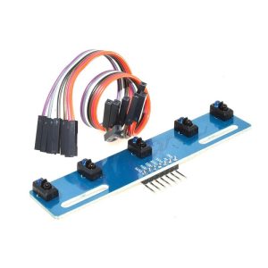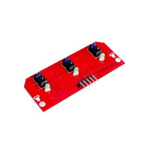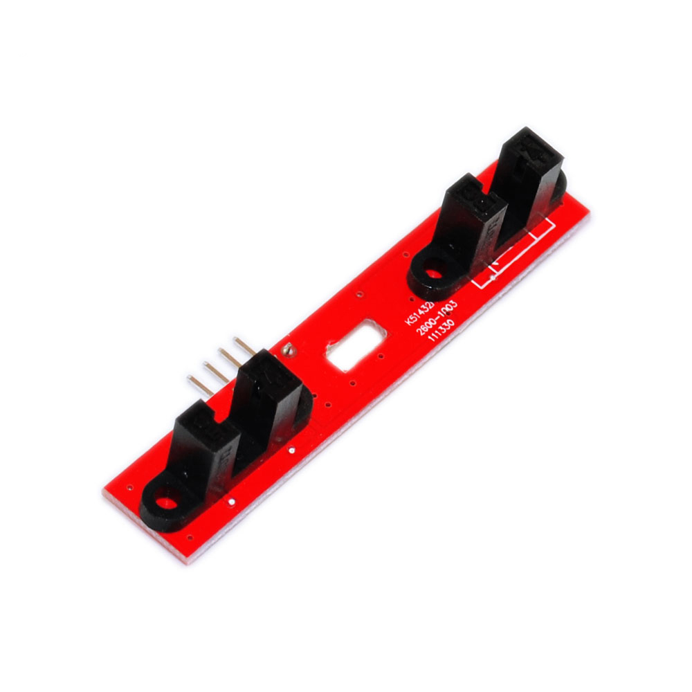
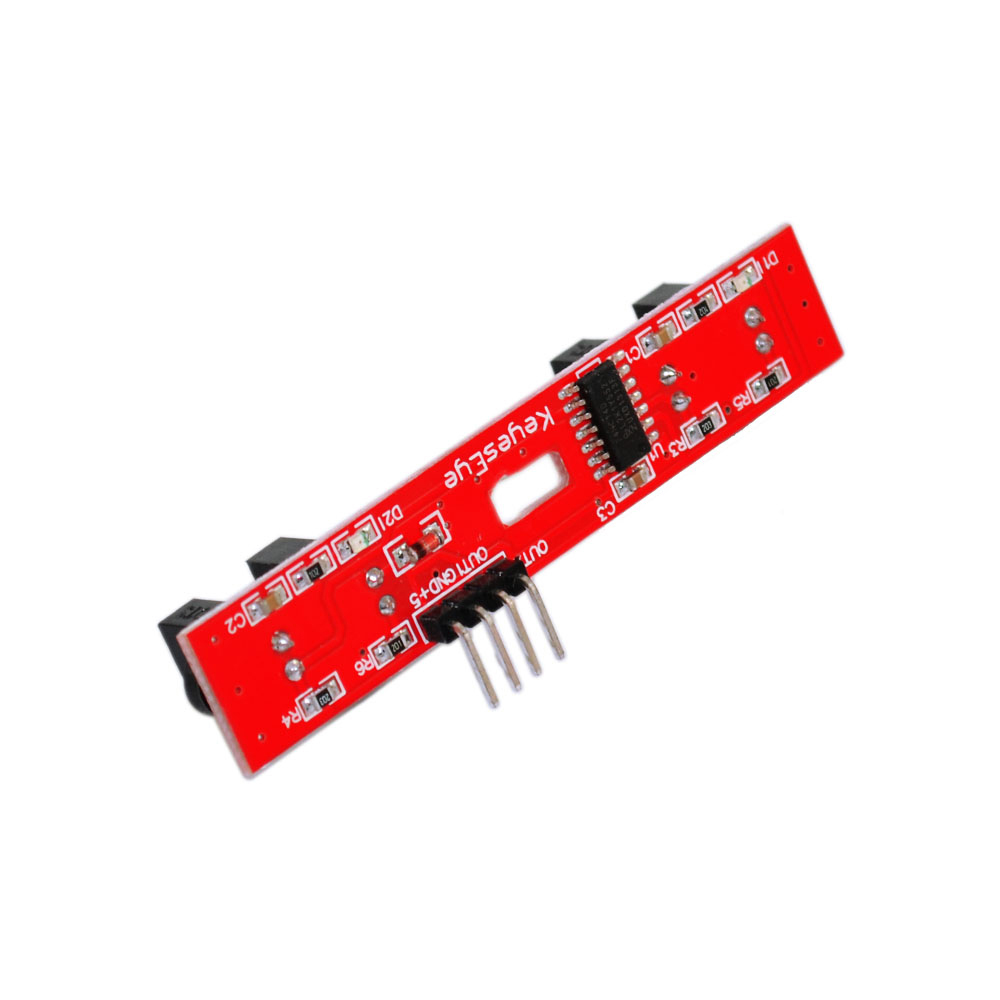
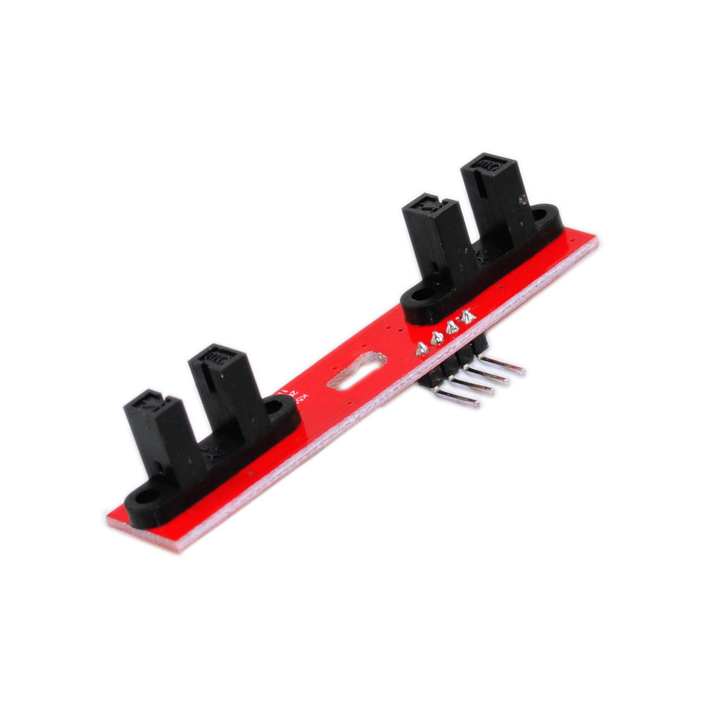
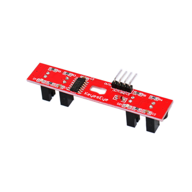
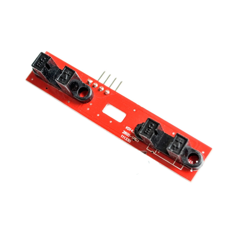
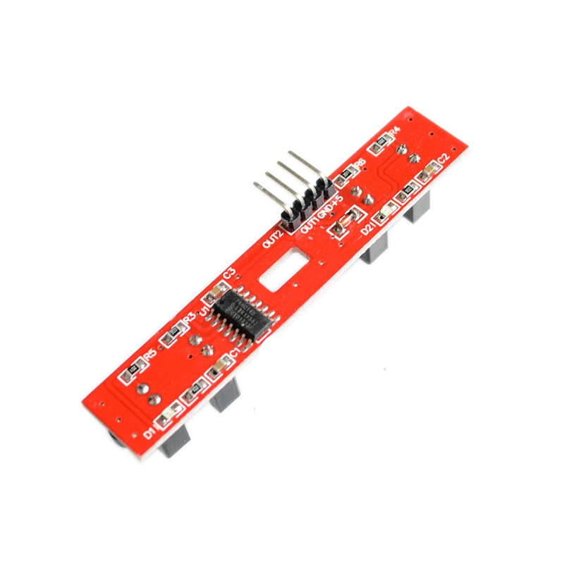
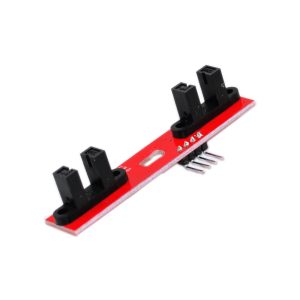
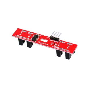
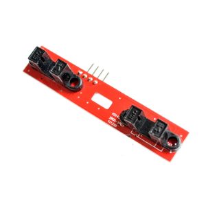
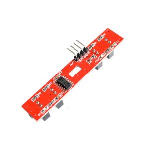
The 2WD Speed Measurement Module is a compact, dual-channel motor speed sensor designed for smart tracking cars, robotics projects, and DIY electronics. It uses photoelectric interrupt technology to measure the rotational speed of two motors simultaneously, providing precise speed and distance data for your microcontroller. This makes it an ideal solution for line-following robots, odometry tracking, PID speed control, and any application requiring accurate motor feedback.
At the heart of the module are two independent photoelectric interrupt sensors, each consisting of an infrared emitter and receiver pair. The sensor detects the rotation of a slotted encoder disc (typically attached to the motor shaft) by counting the interruptions in the infrared beam as the disc rotates. Each interruption generates a digital pulse, which the microcontroller can count to determine the motor’s speed and direction.
The module features dual-channel outputs (typically labeled OUT1 and OUT2 or A and B), one for each motor. Each channel provides a digital square wave whose frequency is proportional to the motor’s rotational speed. By counting the pulses over a fixed time period, you can calculate the RPM (revolutions per minute) and, using the wheel diameter, the linear speed and distance traveled. This makes the module essential for odometry and dead reckoning in autonomous robots.
The module operates from a 3.3V to 5V DC supply, making it compatible with Arduino, ESP32, STM32, and other microcontrollers. The compact PCB design with mounting holes allows easy integration into robot chassis and custom enclosures. The red PCB color provides easy identification in your project.
The photoelectric interrupt principle offers several advantages over mechanical encoders: no contact wear, high reliability, fast response time, and long lifespan. The module is widely used in line-following robots, smart cars, obstacle avoidance robots, PID speed control systems, odometry tracking, motor testing, and educational STEM projects.
Important Note: The module requires a slotted encoder disc (not included) to be attached to the motor shaft for operation. The sensor detects the interruptions in the infrared beam as the disc rotates. Ensure the disc is properly aligned with the sensor’s slot for reliable counting. The module is not waterproof and should be kept dry.
Whether you are building a line-following robot, a smart car, or a PID-controlled motor system, the 2WD Speed Measurement Module provides a reliable, affordable solution for dual-channel motor speed sensing. It is suitable for individual makers, students, and businesses purchasing in bulk for product development or educational programs.
Features
-
Dual-channel speed sensing — Measures two motors simultaneously
-
Photoelectric interrupt technology — Non-contact, wear-free operation
-
Digital pulse output — Frequency proportional to motor speed
-
Wide voltage range — 3.3V to 5V DC, compatible with Arduino, ESP32, STM32
-
Fast response time — Suitable for high-speed motor applications
-
Long lifespan — No mechanical wear, unlike mechanical encoders
-
Compact PCB design — With mounting holes for easy integration
-
Red PCB color — Easy identification in your project
-
Wide application range — Line-following robots, smart cars, odometry, PID control
-
Cost-effective — Affordable solution for motor speed sensing in volume production
Technical Specifications
| # | Parameter | Specification |
|---|---|---|
| 1 | Module Type | Dual-channel photoelectric speed sensor |
| 2 | Number of Channels | 2 independent channels |
| 3 | Sensor Type | Photoelectric interrupt (IR emitter + receiver) |
| 4 | Operating Voltage | 3.3V – 5V DC |
| 5 | Output Type | Digital pulse (square wave) |
| 6 | Response Time | Fast (suitable for high-speed motors) |
| 7 | Pin Count | 5–6 pins (VCC, GND, OUT1, OUT2) |
| 8 | Module Dimensions | Compact PCB with mounting holes |