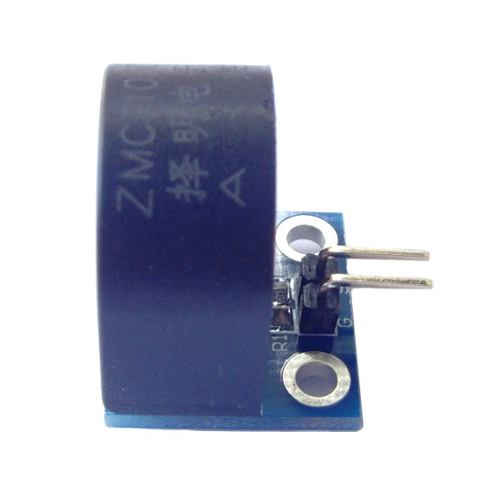
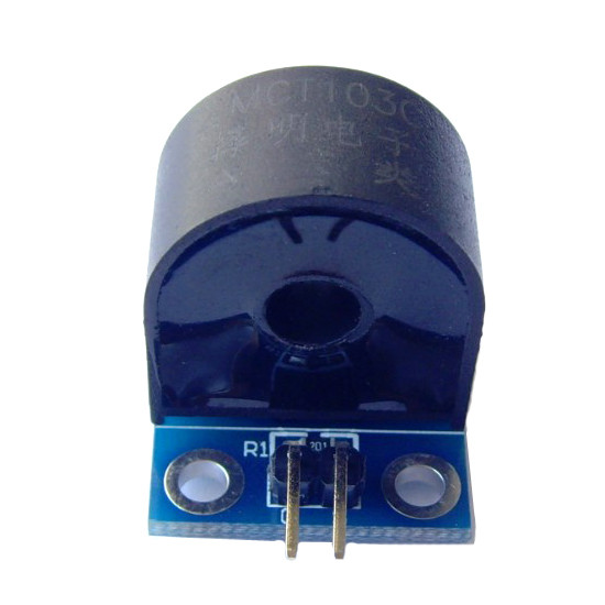
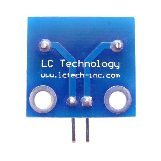
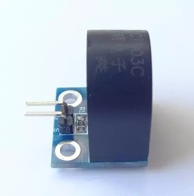
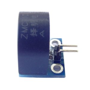
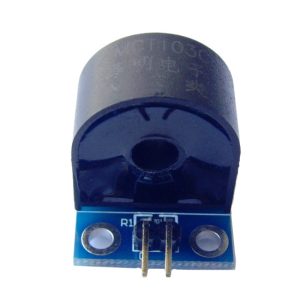
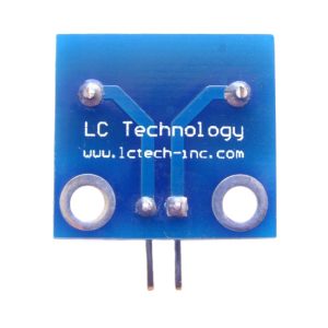
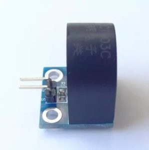
The 5A Single-Phase AC Current Sensor Module is a compact, high-precision current sensing board designed for measuring alternating current (AC) in energy monitoring, load management, and protection applications. Built around the ZMCT103C precision micro current transformer, this module provides galvanic isolation between the high-voltage AC line and the low-voltage measurement circuit, ensuring safe and accurate current sampling for microcontrollers like Arduino, ESP32, and Raspberry Pi.
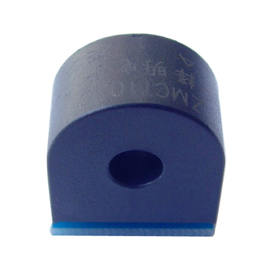
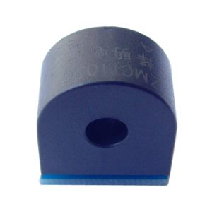
At the heart of the module is the ZMCT103C current transformer, a PCB-mount device with a 1000:1 turns ratio. When the primary AC current flows through the conductor passing through the transformer’s center hole, the secondary winding produces a proportional current. At the rated input of 5A, the output is 5mA . The onboard sampling resistor converts this current into a measurable voltage signal, while the high-precision operational amplifier circuit (on active-output variants) amplifies and conditions the signal for direct connection to an ADC input .
The module offers adjustable output via an onboard potentiometer on active variants, allowing you to tune the output voltage range for your specific measurement setup. The output signal is an AC voltage waveform that corresponds proportionally to the primary AC current, with the maximum output voltage typically capped at 1/2 VCC . The module operates from a DC supply (typically 5V, with some variants supporting 3–35V), making it compatible with standard microcontroller power rails .
Important Note: This module outputs an analog AC signal, not a DC voltage. To read it with a microcontroller ADC, you must either bias the signal to mid-rail (using a voltage divider or op-amp level shifter) or use a bridge rectifier and filter capacitor to convert it to a proportional DC voltage . The transformer provides galvanic isolation (typically rated 3000V–4500V), but proper safety precautions are still required when working with mains AC . The module is not intended for DC current measurement. For precise energy metering applications, calibration against a known reference load is recommended.
Whether you are building a home energy monitor, a solar panel current tracker, or an industrial load monitoring system, the ZMCT103C module provides a reliable, isolated solution for AC current sensing.
Features
-
ZMCT103C precision current transformer — 1000:1 turns ratio for accurate AC current sensing
-
Galvanic isolation — Separates high-voltage AC line from low-voltage measurement circuit for safety
-
Onboard sampling resistor — Converts transformer output current to a measurable voltage signal
-
High-precision op-amp circuit (active variants) — Amplifies and conditions the signal for direct ADC input
-
Adjustable output — Potentiometer allows tuning of output voltage range
-
Wide supply voltage (variant dependent) — Some variants support 3–35V DC operation
-
Compact PCB form factor — Approx. 18 × 19mm for easy integration
-
Wide linear range — 0–10A (with 100Ω load) for measurement headroom beyond the 5A rating
-
High linearity — 0.2% for accurate current-to-voltage conversion
-
Wide application range — Energy metering, motor monitoring, overcurrent protection, solar systems
Technical Specifications
Usage
Getting Started
-
Connect the AC load — Pass the live AC wire through the center hole of the current transformer. Only one conductor should pass through; passing both live and neutral will cancel the magnetic field and produce no output.
-
Connect power — Supply the module’s VCC and GND with the appropriate DC voltage (typically 5V). The onboard op-amp will power up.
-
Connect the output — Connect the OUT pin to an analog input on your microcontroller. Remember: the output is an AC waveform, not a DC level.
-
Bias the signal (if using ADC directly) — To read the AC waveform with a microcontroller ADC, you must add a DC bias (typically VCC/2) so the signal swings positive. Use a resistor divider or an op-amp level shifter.
-
Rectify and filter (alternative method) — For simpler RMS or average readings, add a bridge rectifier and a filter capacitor to convert the AC output to a proportional DC voltage .
-
Calibrate — Apply a known AC load (e.g., a resistive heater or incandescent lamp) and note the ADC reading. Calculate the scaling factor for your application.
Pin Connections (Typical)
Example Arduino Code (RMS Calculation with Bias)
#define CT_PIN A0
#define VCC 5.0
#define BIAS 2.5
#define SENSITIVITY 0.185
void setup() {
Serial.begin(9600);
}
void loop() {
float sumSquares = 0;
int samples = 2000;
for (int i = 0; i < samples; i++) {
int raw = analogRead(CT_PIN);
float voltage = raw * (VCC / 1023.0);
float centered = voltage - BIAS;
sumSquares += centered * centered;
}
float rmsVoltage = sqrt(sumSquares / samples);
float current = rmsVoltage / SENSITIVITY;
Serial.print("RMS Current: ");
Serial.print(current, 3);
Serial.println(" A");
delay(1000);
}
Note: The SENSITIVITY value must be calibrated for your specific module and load. This example assumes a biased AC signal at the ADC input.
Typical Applications
-
Energy monitoring — Track AC current consumption of appliances and equipment
-
Overcurrent protection — Detect fault conditions and trigger protective relays
-
Motor current monitoring — Track motor load for maintenance and fault detection
-
Solar power systems — Monitor AC output from inverters
-
Load measurement — Measure current drawn by electrical devices for load management
Notes for Business Buyers
-
AC signal output — Requires biasing or rectification before ADC reading; factor this into your design.
-
Isolation is provided — But proper safety practices for mains voltage are still mandatory.
-
Active vs. passive variants — Verify your module includes the op-amp circuit if you need amplified output; passive variants output raw transformer current only.
-
Suitable for bulk purchasing — Ideal for energy monitor manufacturers, industrial control integrators, and educational institutions.
Q: What is the ZMCT103C module used for?
It is an AC current sensor for measuring alternating current up to 5A, used in energy monitoring, overcurrent protection, motor monitoring, and solar power systems.
Q: What is the output signal of this module?
The output is an analog AC voltage waveform proportional to the primary AC current. It is not a DC voltage and must be biased or rectified before reading with a standard ADC .
Q: Can I connect the output directly to an Arduino analog pin?
Not directly for meaningful readings. The AC signal swings negative and positive. You must add a DC bias (typically VCC/2) or use a rectifier and filter to convert it to a DC voltage .
Q: What is the turns ratio of the ZMCT103C?
The ZMCT103C has a 1000:1 turns ratio. At 5A input, the output is 5mA .
Q: Does this module provide galvanic isolation?
Yes. The current transformer provides galvanic isolation between the AC line and the measurement circuit, typically rated 3000V–4500V .
Q: Can I measure DC current with this module?
No. This is a current transformer designed for AC current only. It will not respond to DC current.
Q: What is the linear range of the module?
The linear range is 0–10A with a 100Ω load, providing measurement headroom beyond the 5A rated input .
Q: How do I calibrate the module for accurate readings?
Apply a known AC load (e.g., a resistive heater with a known wattage) and note the ADC reading. Use this to calculate your scaling factor (Amps per ADC unit or Amps per Volt).
Q: Is this module safe to use with mains voltage?
The transformer provides isolation, but proper safety precautions are mandatory when working with mains AC. Ensure the module and wiring are properly insulated and enclosed.
Q: Can I purchase in bulk for a product development project?
Yes. This module is suitable for bulk purchasing by energy monitor manufacturers, industrial control integrators, and educational institutions.