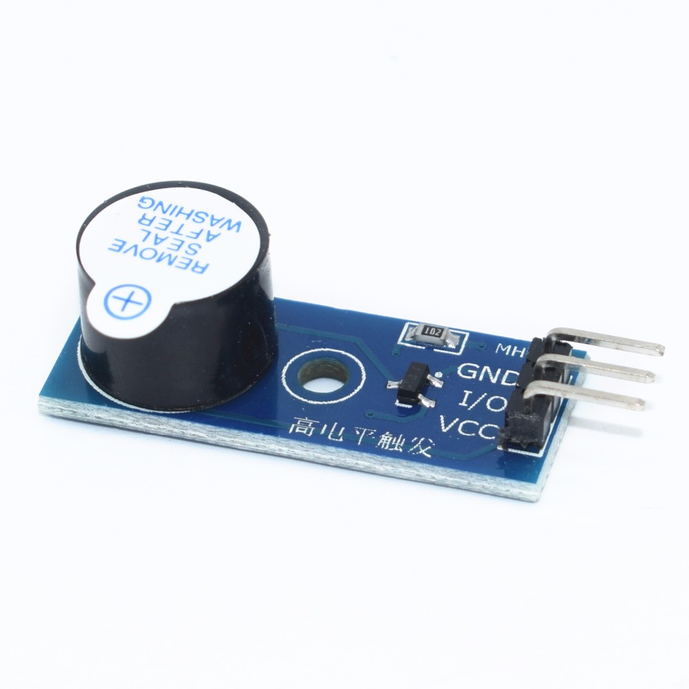
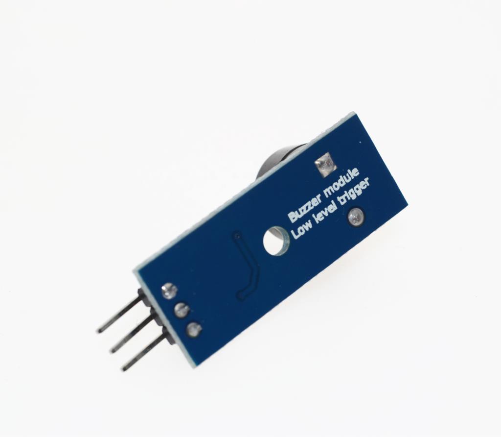
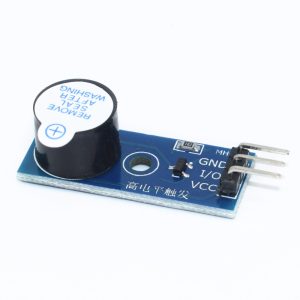
The 5V Active Buzzer Control Board with Low-Level Trigger is a compact, ready-to-use sound alarm module designed for Arduino, ESP32, Raspberry Pi, STM32, and other microcontroller projects. Unlike bare buzzer components that require external driver circuitry, this module integrates an active buzzer, a transistor driver circuit, and protection components on a single PCB — making it the simplest way to add audible alerts and notifications to your projects without any additional wiring or component selection.
At the heart of the module is an active electromagnetic buzzer with a built-in oscillator. When powered, the buzzer produces a fixed-frequency tone (typically around 2.3kHz to 3.5kHz) — no PWM signal or frequency generation is required. The onboard transistor driver amplifies the microcontroller’s control signal to drive the buzzer at the required current, ensuring reliable operation without overloading the MCU’s output pin. The onboard protection components (including a flyback diode and current-limiting resistor) protect both the buzzer and the microcontroller from voltage spikes and overcurrent conditions.
The low-level trigger design is a key feature of this module. When the input signal is LOW (0V) , the buzzer sounds. When the input signal is HIGH (VCC) , the buzzer is silent. This active-low logic is convenient for many control applications, including open-collector outputs, PLC sinking outputs, and microcontroller pins configured with internal pull-ups. An LED indicator provides visual feedback when the buzzer is activated, making it easy to verify operation during setup and troubleshooting.
The module features a 3-pin interface (VCC, GND, I/O or IN) for easy connection to microcontrollers. The signal pin accepts a digital signal — LOW turns the buzzer on, HIGH turns it off. The compact PCB form factor with mounting holes allows easy integration into alarm systems, notification devices, and control panels.
The module operates from a 5V DC supply (some variants support 3.3V to 5V), making it compatible with Arduino, ESP32, Raspberry Pi, and other common microcontrollers. The low power consumption makes it suitable for battery-powered alarm and notification projects.
The 5V Active Buzzer Control Board is widely used in alarm systems, notification devices, doorbells, timers, game controllers, interactive toys, security systems, industrial control panels, PLC output indication, and educational STEM projects. It is also popular in DIY electronics and maker projects where reliable audible feedback is required.
Important Note: This module uses an active buzzer — it produces a fixed tone when powered and cannot play melodies or variable frequencies. For variable tones or music, use a passive buzzer module with PWM control instead. The low-level trigger means the buzzer sounds when the input is LOW — verify your control logic accordingly. The module is not waterproof and should be kept dry. Avoid continuous operation at high volume for extended periods, as this may cause the buzzer to overheat or degrade over time.
Whether you are building an alarm system, a notification device, or an industrial control panel, the 5V Active Buzzer Control Board with Low-Level Trigger provides a reliable, integrated solution for audible feedback. It is suitable for individual makers, students, and businesses purchasing in bulk for product development or educational programs.
Features
-
Integrated active buzzer — Built-in oscillator produces sound when powered
-
Low-level trigger — Buzzer sounds when input is LOW (0V)
-
Onboard transistor driver — Reliable operation without overloading MCU pins
-
Protection components onboard — Flyback diode and current-limiting resistor
-
LED indicator — Visual feedback when buzzer is activated
-
3-pin interface — VCC, GND, I/O for simple connection
-
Wide voltage range — 5V DC (some variants support 3.3V–5V)
-
Compact PCB form factor — With mounting holes for easy integration
-
Wide application range — Alarms, notifications, doorbells, timers, industrial panels
-
Cost-effective — Affordable solution for sound output in volume production
Technical Specifications
| # | Parameter | Specification |
|---|---|---|
| 1 | Module Type | Active buzzer control board |
| 2 | Buzzer Type | Active electromagnetic buzzer (built-in oscillator) |
| 3 | Operating Voltage | 5V DC (3.3V–5V variants available) |
| 4 | Trigger Type | Low-level trigger (LOW = ON, HIGH = OFF) |
| 5 | Sound Output | Fixed tone, approximately 2.3kHz–3.5kHz |
| 6 | Driver Type | Onboard transistor |
| 7 | Indication | LED indicator |
| 8 | Pin Count | 3 pins (VCC, GND, I/O) |