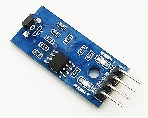
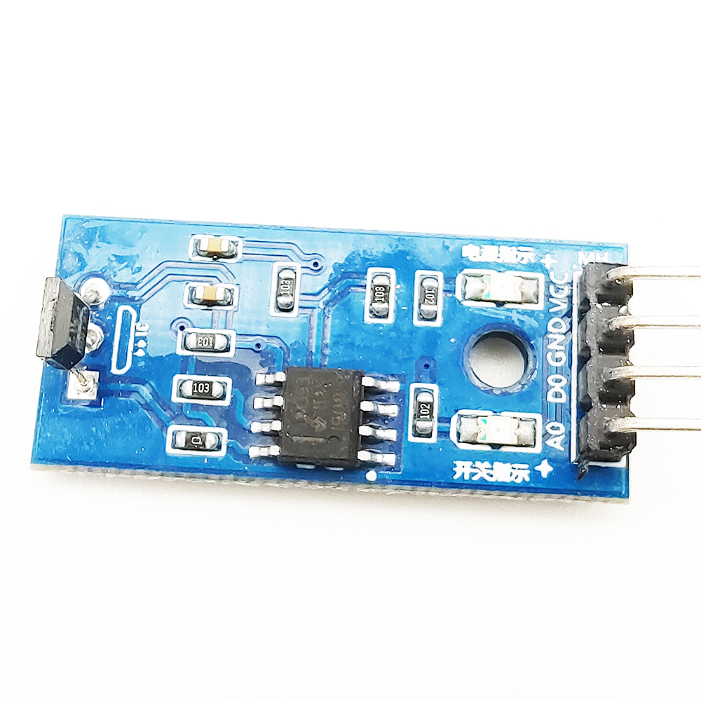
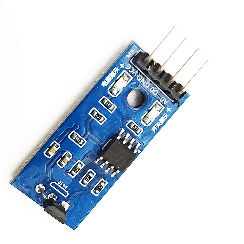
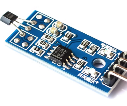
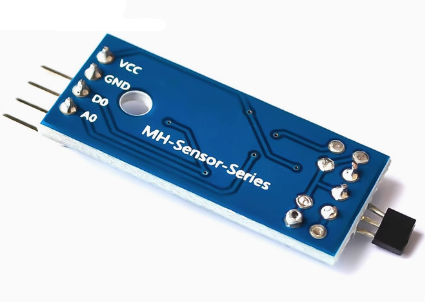
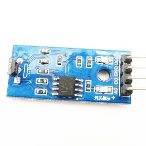
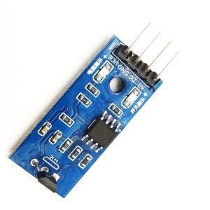
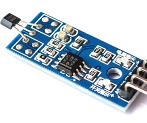
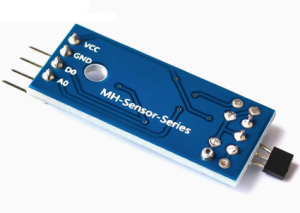
The Hall Effect Speed Sensor Module (No Potentiometer) is a compact, reliable magnetic sensing board designed specifically for speed measurement, RPM counting, and tachometer applications. Unlike Hall sensor modules with an analog output and adjustable potentiometer, this version provides a single digital output that pulses when a magnetic field is detected — making it simpler to use, easier to integrate, and ideal for high-speed counting and tachometer applications in motor control, automation, and robotics.
At the heart of the module is a Hall Effect sensor IC that responds to magnetic field changes. When a magnetic target (such as a small magnet attached to a rotating shaft) passes near the sensor, the Hall element detects the field and switches the digital output between HIGH and LOW states. Each transition generates a pulse that can be counted by a microcontroller, PLC, or dedicated tachometer circuit. By counting the pulses over a known time period and knowing the number of magnets per revolution, you can calculate RPM (revolutions per minute) and linear speed.
The “No Potentiometer” design is a key advantage of this module. By removing the adjustable potentiometer, the module offers:
-
Simpler operation — No sensitivity adjustment required; ready to use out of the box
-
More compact form factor — Smaller PCB footprint for space-constrained installations
-
Higher reliability — Fewer mechanical components that can drift or fail over time
-
Consistent performance — Fixed threshold optimized for common magnet strengths and air gaps
The module features LED indicators for power status and magnetic detection, providing visual feedback during setup and troubleshooting. The digital output can be connected directly to a microcontroller’s digital input pin, with interrupt-driven pulse counting recommended for accurate high-speed measurement. The output is compatible with both 3.3V and 5V logic systems.
The module operates from a 3.3V to 5V DC supply (industrial variants may support 5V–24V), making it compatible with Arduino, ESP32, STM32, Raspberry Pi, and industrial control systems. The compact form factor with mounting holes allows easy integration into motor housings, conveyor systems, and automation equipment. The screw terminals or pin headers provide secure connections for power and signal wiring.
The Hall Effect Speed Sensor Module is widely used in motor speed measurement, RPM counters, tachometers, flow meters, conveyor belt monitoring, CNC spindle speed sensing, robotics wheel speed feedback, and industrial automation. It is also popular in educational projects for teaching magnetic sensing and pulse counting principles.
Important Note: The Hall Effect sensor detects magnetic fields, so a magnet must be attached to the rotating or moving target for speed measurement. The air gap between the sensor and the magnet affects detection reliability — keep the gap as small as practical (typically 1–10mm depending on magnet strength). Because there is no potentiometer, the detection threshold is fixed; if your magnet is too weak or the air gap is too large, detection may be unreliable. The module is not waterproof and should be kept dry. For industrial environments, ensure proper shielding and cable routing to avoid electromagnetic interference.
Whether you are building a motor speed controller, a tachometer, or an industrial counting system, the Hall Effect Speed Sensor Module (No Potentiometer) provides a reliable, simple solution for digital speed measurement. It is suitable for individual makers, engineers, and businesses purchasing in bulk for product development or industrial applications.
Features
-
Hall Effect magnetic sensing — Detects magnetic field changes for speed and RPM measurement
-
Digital output only — Clean HIGH/LOW pulse for easy counting and tachometer applications
-
No potentiometer — Fixed threshold for simpler operation and higher reliability
-
Compact form factor — Smaller PCB footprint than adjustable versions
-
LED indicators — Power status and magnetic detection feedback
-
Wide voltage range — 3.3V to 5V DC (5V–24V industrial variants available)
-
Interrupt-friendly output — Suitable for high-speed pulse counting
-
Mounting holes — Easy integration into motor housings and automation equipment
-
Wide application range — Motor speed, RPM counting, tachometer, flow meters, conveyor monitoring
-
Cost-effective — Affordable solution for speed measurement in volume production
Technical Specifications
| # | Parameter | Specification |
|---|---|---|
| 1 | Sensor Type | Hall Effect magnetic sensor |
| 2 | Output Type | Digital (pulse) only |
| 3 | Operating Voltage | 3.3V – 5V DC (5V–24V variants available) |
| 4 | Detection Method | Magnetic field detection |
| 5 | Sensitivity Adjustment | None (fixed threshold) |
| 6 | Indication | Power LED + detection LED |
| 7 | Pin Count | 3 pins (VCC, GND, DO) |
| 8 | Module Dimensions | Compact PCB with mounting holes |