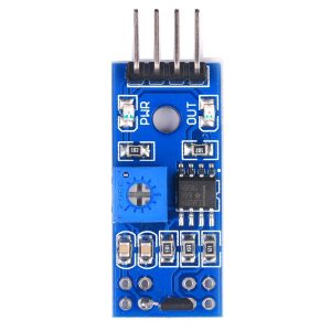
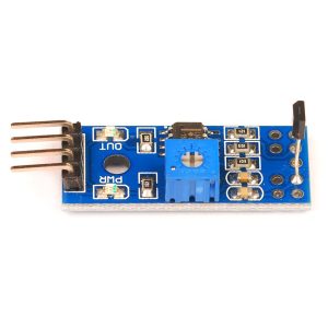
Hall Effect Sensor Module – Speed Measurement & Counter Sensor for Industrial Automation (Digital/Analog Output)

SKU: FA3025-1
Sensor Type

Hall Effect magnetic sensor

Output Type

Digital (DO) + Analog (AO)

Operating Voltage

3.3V – 5V DC (5V–24V variants available)

Detection Method

Magnetic field detection

Sensitivity Adjustment

Onboard potentiometer

Indication

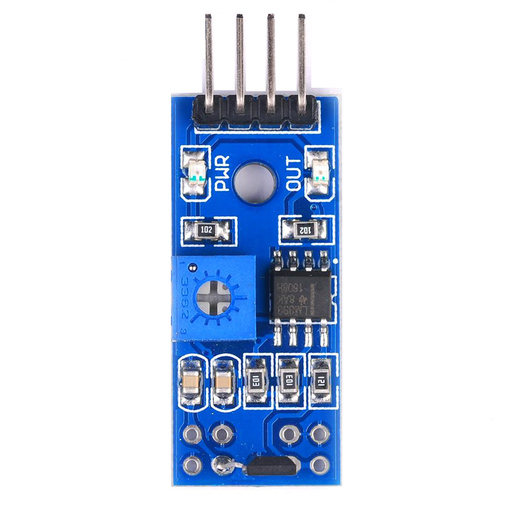
Power LED + detection LED

Pin Count

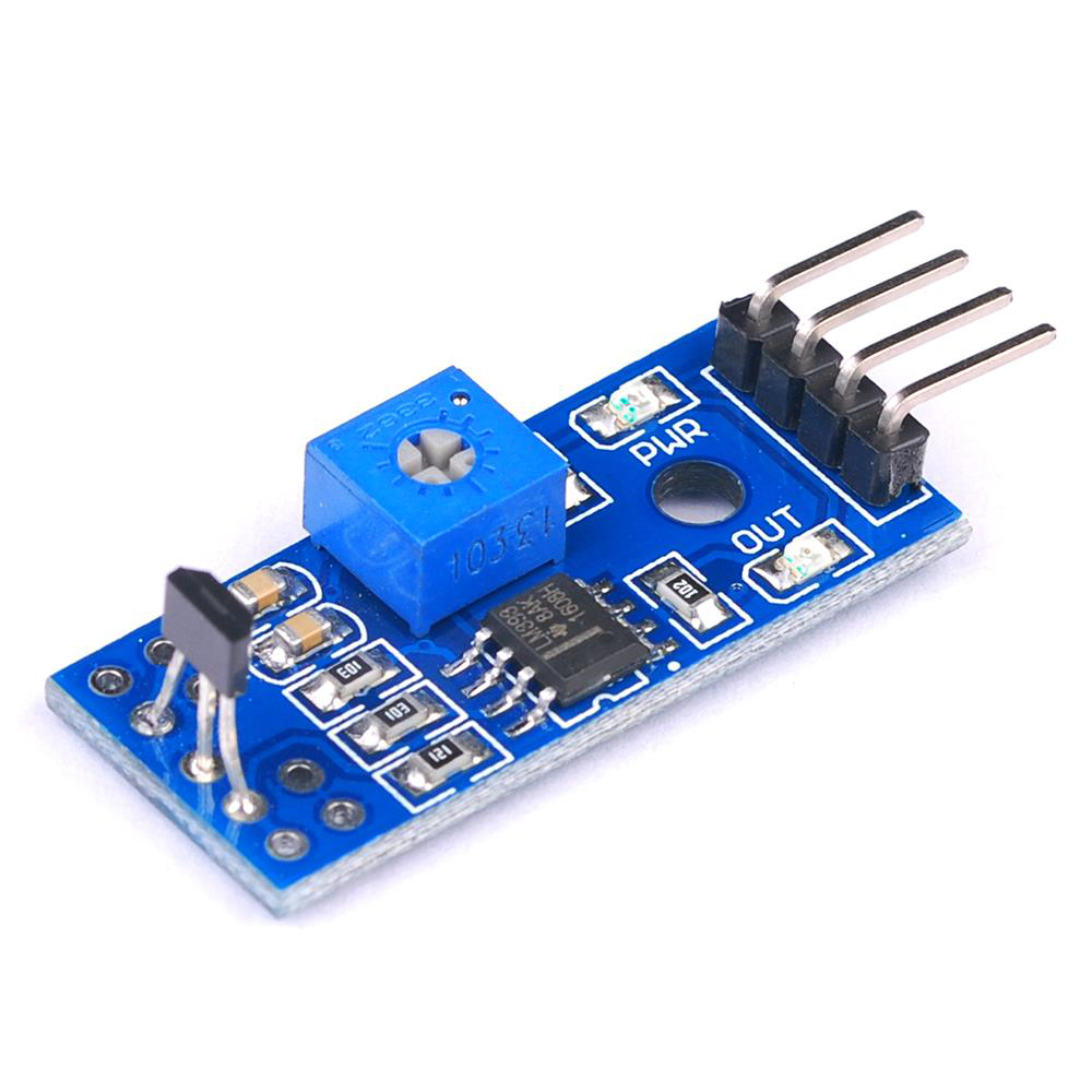
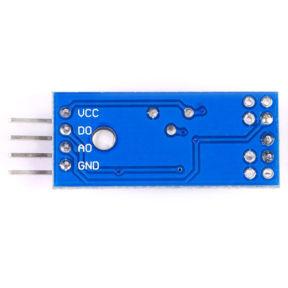
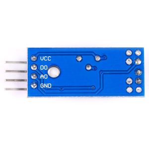
4 pins (VCC, GND, DO, AO)

Module Dimensions

Compact PCB with mounting holes

The Hall Effect Sensor Module is a versatile, industrial-grade magnetic sensing board designed for speed measurement, pulse counting, position detection, and proximity sensing. Built around a Hall Effect sensor IC with both digital and analog outputs, this module detects the presence of magnetic fields and converts them into clean electrical signals for microcontrollers, PLCs, and industrial control systems. It is an ideal solution for motor speed measurement, RPM counting, flow meters, proximity detection, and automation equipment.

At the heart of the module is a Hall Effect sensor that responds to magnetic field changes. When a magnetic target (such as a magnet attached to a rotating shaft) passes near the sensor, the Hall element detects the field and triggers an output. The module provides two output types:

  • Digital Output (DO) — A clean HIGH/LOW signal that switches when a magnetic field is detected, ideal for pulse counting and speed measurement.

  • Analog Output (AO) — A continuous voltage proportional to the magnetic field strength, allowing for position and proximity measurement.

The digital output is the primary interface for speed measurement and counting applications. By attaching a magnet to a rotating shaft and counting the pulses generated per revolution, you can calculate RPM (revolutions per minute) and linear speed. The analog output provides additional information about magnetic field strength, useful for position sensing and gap measurement between the sensor and the target.

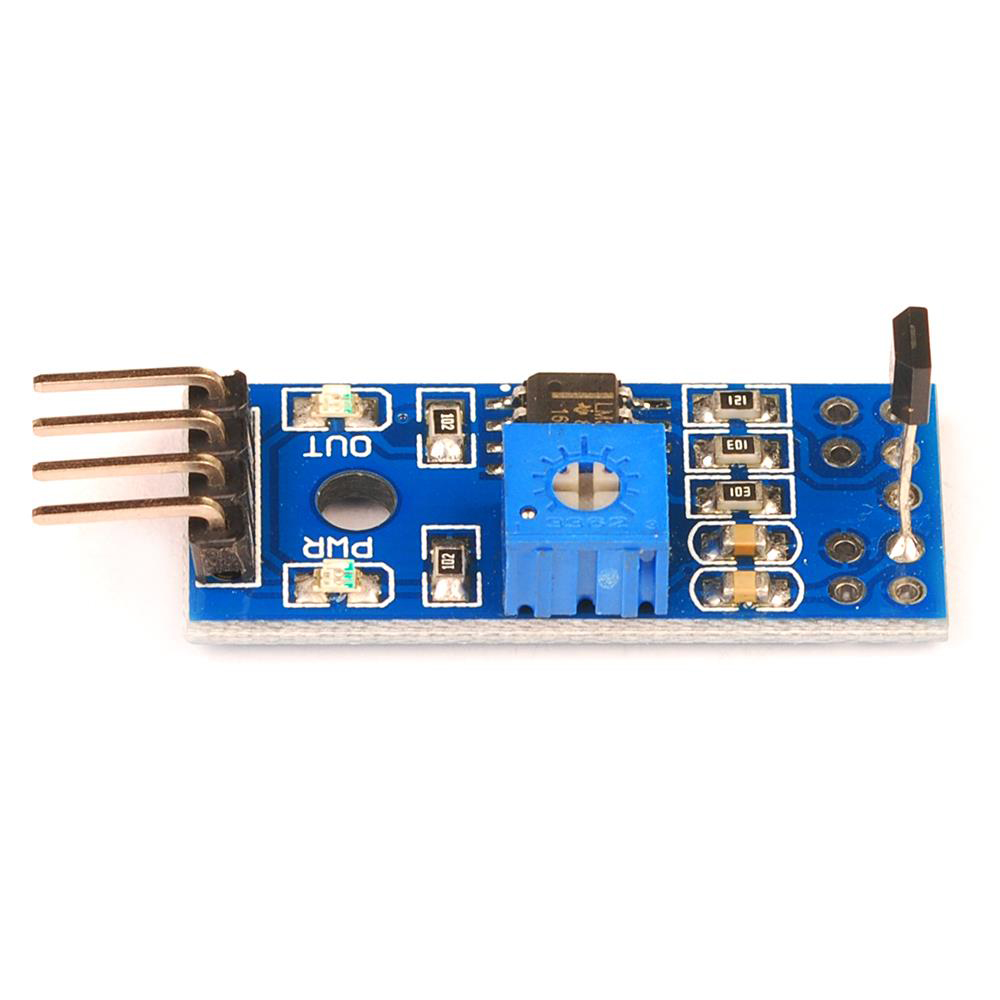
The module features an onboard potentiometer for adjusting the digital output threshold, allowing you to optimize sensitivity for different magnet strengths and air gaps. LED indicators provide visual feedback for power status and magnetic detection, making it easy to verify operation during setup and troubleshooting.

The module operates from a 3.3V to 5V DC supply (or 5V–24V for industrial variants), making it compatible with Arduino, ESP32, STM32, Raspberry Pi, and industrial control systems. The compact form factor with mounting holes allows easy integration into motor housings, conveyor systems, and automation equipment. The screw terminals or pin headers provide secure connections for power and signal wiring.

The Hall Effect Sensor Module is widely used in motor speed measurement, RPM counters, flow meters, proximity detection, position sensing, anti-lock braking systems (ABS), conveyor belt monitoring, CNC spindle speed sensing, and industrial automation. It is also popular in educational projects for teaching magnetic sensing and pulse counting principles.

Important Note: The Hall Effect sensor detects magnetic fields, so a magnet must be attached to the rotating or moving target for speed and position measurement. The air gap between the sensor and the magnet affects detection reliability — keep the gap as small as practical (typically 1–10mm depending on magnet strength). The module is not waterproof and should be kept dry. For industrial environments, ensure proper shielding and cable routing to avoid electromagnetic interference.

Whether you are building a motor speed controller, a flow meter, or an industrial counting system, the Hall Effect Sensor Module provides a reliable, versatile solution for magnetic sensing and speed measurement. It is suitable for individual makers, engineers, and businesses purchasing in bulk for product development or industrial applications.

Features

  • Hall Effect magnetic sensing — Detects magnetic field changes for speed and position measurement

  • Dual outputs — Digital (DO) for pulse counting and Analog (AO) for field strength

  • Speed measurement capability — Count pulses to calculate RPM and linear speed

  • Adjustable sensitivity — Onboard potentiometer for digital output threshold

  • LED indicators — Power status and magnetic detection feedback

  • Wide voltage range — 3.3V to 5V DC (5V–24V industrial variants available)

  • Compact form factor — With mounting holes for easy integration

  • Screw terminals or pin headers — Secure connections for power and signal

  • Wide application range — Motor speed, RPM counting, flow meters, proximity detection

  • Industrial-grade reliability — Suitable for automation and control systems

Technical Specifications 

# Parameter Specification
1 Sensor Type Hall Effect magnetic sensor
2 Output Type Digital (DO) + Analog (AO)
3 Operating Voltage 3.3V – 5V DC (5V–24V variants available)
4 Detection Method Magnetic field detection
5 Sensitivity Adjustment Onboard potentiometer
6 Indication Power LED + detection LED
7 Pin Count 4 pins (VCC, GND, DO, AO)
8 Module Dimensions Compact PCB with mounting holes

Usage

Getting Started

  1. Connect power — Supply 3.3V or 5V DC to the VCC pin and GND to ground.

  2. Connect the outputs — Connect the DO pin to a digital input on your microcontroller (e.g., D2 on Arduino, interrupt-capable pin recommended). Connect the AO pin to an analog input if field strength measurement is needed.

  3. Mount the sensor — Position the sensor so it faces the path of the magnetic target. Attach a magnet to the rotating shaft or moving object.

  4. Adjust sensitivity — Use the onboard potentiometer to set the detection threshold for the digital output.

  5. Upload a test sketch — Read the digital output to count pulses, or read the analog output to measure field strength.

  6. Calculate speed — Count pulses per time period and use the known number of magnets per revolution to calculate RPM or linear speed.

Pin Connections

Module Pin Function
VCC Power (3.3V–5V)
GND Ground
DO Digital output (pulse when magnet detected)
AO Analog output (field strength)

Speed Calculation

Parameter Formula
RPM (Pulses per second / Magnets per revolution) × 60
Linear Speed RPM × Wheel Circumference / 60
Distance Total Pulses / Magnets per revolution × Wheel Circumference

Example Arduino Code (Pulse Counting)

cpp
#define HALL_PIN 2

volatile int pulseCount = 0;

void setup() {
  Serial.begin(9600);
  pinMode(HALL_PIN, INPUT_PULLUP);
  attachInterrupt(digitalPinToInterrupt(HALL_PIN), countPulse, FALLING);
}

void countPulse() {
  pulseCount++;
}

void loop() {
  pulseCount = 0;
  delay(1000);
  Serial.print("Pulses per second: ");
  Serial.println(pulseCount);

  // Calculate RPM (assuming 1 magnet per revolution)
  float rpm = pulseCount * 60.0;
  Serial.print("RPM: ");
  Serial.println(rpm);
}

Typical Applications

  • Motor speed measurement — RPM monitoring for DC motors and spindles

  • Flow meters — Count rotations of a magnetic impeller

  • Proximity detection — Detect the presence of magnetic objects

  • Position sensing — Measure linear or angular position with magnetic targets

  • Conveyor belt monitoring — Count items or measure belt speed

  • Anti-lock braking systems (ABS) — Wheel speed sensing

  • CNC spindle speed sensing — Monitor spindle RPM for feed control

  • Educational STEM projects — Teaching magnetic sensing and pulse counting

Notes for Business Buyers

  • Dual outputs — Digital for counting, analog for field strength measurement.

  • Adjustable sensitivity — Potentiometer adapts to different magnet strengths and air gaps.

  • Industrial-grade reliability — Suitable for automation, motor control, and counting applications.

  • Suitable for bulk purchasing — Ideal for motor control manufacturers, automation integrators, and educational institutions.

Q: What is the Hall Effect Sensor Module used for?

It is a magnetic sensing module for speed measurement, pulse counting, position detection, and proximity sensing, used in motor control, flow meters, and industrial automation.

Q: What is the difference between the digital and analog outputs?

The digital output (DO) provides a clean HIGH/LOW pulse when a magnetic field is detected, ideal for counting and speed measurement. The analog output (AO) provides a continuous voltage proportional to magnetic field strength, useful for position and gap measurement.

Q: How do I measure motor speed with this module?

Attach a magnet to the rotating shaft, position the sensor to detect the magnet, and count the digital pulses per time period. Use the formula: RPM = (Pulses per second / Magnets per revolution) × 60.

Q: What voltage does the module require?

It operates from 3.3V to 5V DC (industrial variants may support 5V–24V).

Q: How do I adjust the sensitivity?

Use the onboard potentiometer to set the detection threshold for the digital output. Adjust until the LED indicates reliable detection of your magnet.

Q: Does the module require a magnet?

Yes. The Hall Effect sensor detects magnetic fields, so a magnet must be attached to the rotating or moving target for speed and position measurement.

Q: What is the recommended air gap?

Keep the gap between the sensor and the magnet as small as practical, typically 1–10mm depending on magnet strength. Larger gaps may reduce detection reliability.

Q: Can I use this module with an Arduino?

Yes. Connect VCC to 5V, GND to GND, DO to a digital pin (e.g., D2), and AO to an analog pin (e.g., A0). Use interrupt-driven pulse counting for accurate speed measurement.

Q: Is the module waterproof?

No. The module is not waterproof and should be kept dry.

Q: Can I purchase in bulk for an industrial project?

Yes. This module is suitable for both individual users and business purchasing, including motor control manufacturers, automation integrators, and educational institutions.