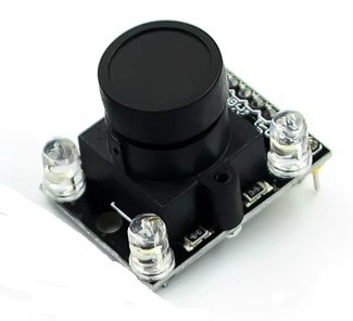
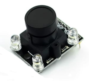
TCS230 TCS3200D Color Recognition Sensor Module with Wide-Angle Lens – High Accuracy RGB Detection Board

SKU: FA3023-3
Sensor IC

TAOS TCS230 / TCS3200D

Photodiode Array

64 photodiodes (16 red, 16 green, 16 blue, 16 clear)

Output Type

Digital frequency (square wave)

Frequency Scaling

2% / 20% / 100% (selectable)

Operating Voltage

2.7V – 5.5V DC

Lens Type

Wide-angle

Onboard LEDs

4× white LEDs

Pin Count

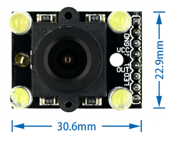
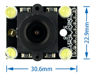
8 pins (VCC, GND, S0, S1, S2, S3, OUT, LED)

The TCS230 / TCS3200D Color Recognition Sensor Module with Wide-Angle Lens is a complete, ready-to-use color detection board designed for Arduino, ESP32, Raspberry Pi, and other microcontroller projects. Built around the TAOS TCS230 / TCS3200D color light-to-frequency converter and equipped with a wide-angle lens, this module enables your project to detect, identify, and differentiate colors with improved field of view and accuracy. It is an ideal solution for color sorting machines, line-following robots, color matching systems, and educational STEM projects.

At the heart of the module is the TCS230 / TCS3200D, a programmable color light-to-frequency converter that combines a configurable silicon photodiode array with a current-to-frequency converter on a single monolithic CMOS integrated circuit. The photodiode array consists of 64 photodiodes arranged in an 8×8 grid, with 16 photodiodes each having red, green, blue, and clear (no filter) filters. By selectively activating the red, green, blue, or clear filters via two control pins (S2 and S3), the sensor measures the intensity of each color component sequentially.

The wide-angle lens is a key feature of this module variant. It expands the sensor’s field of view, allowing it to capture color information from a broader area and making it easier to align with the target object. This is particularly useful in sorting applications where objects may not be perfectly centered, and in line-following robots where the line position may vary. The lens also helps concentrate light onto the photodiode array, improving sensitivity in low-light conditions.

The module outputs a digital square wave whose frequency is directly proportional to the light intensity of the selected color channel. This frequency output is easily read by any microcontroller using a digital input pin and a pulse-counting routine — no ADC required. The output frequency range can be scaled using two additional pins (S0 and S1) to select one of three preset scaling options: 2% (power down), 20%, or 100% , allowing you to optimize the output for different lighting conditions and microcontroller speeds.

The module includes four bright white LEDs arranged around the sensor to provide consistent illumination for reflective color sensing. The LEDs can be left always-on or controlled by a microcontroller pin for power saving. The board also includes current-limiting resistors and decoupling capacitors for stable operation.

The TCS230 / TCS3200D operates from a 2.7V to 5.5V supply, making it compatible with both 3.3V and 5V microcontrollers. The compact form factor with mounting holes allows easy integration into sorting machines, robot chassis, and custom enclosures. The 8-pin interface provides straightforward connection: VCC, GND, S0, S1, S2, S3, OUT, and LED control.

The TCS230 / TCS3200D with wide-angle lens is widely used in color sorting systems, line-following robots (detecting colored lines), color matching devices, product inspection equipment, ambient light sensing, and educational STEM projects. It is also popular in DIY electronics and maker projects where color detection is required.

Important Note: The sensor measures reflected light, so the distance between the sensor and the target object affects readings. For consistent results, maintain a fixed distance (typically 1–3cm) and ensure uniform illumination. The sensor’s output is a frequency, not an absolute color value — you must calibrate the sensor against known color references (white and black) for accurate color identification. The module is not waterproof and should be kept dry. Avoid ambient light interference by using the onboard LEDs and shielding the sensor from external light sources where possible.

Whether you are building a color sorting machine, a line-following robot, or an interactive color detection project, the TCS230 / TCS3200D Color Recognition Sensor Module with Wide-Angle Lens provides a reliable, affordable solution with improved field of view. It is suitable for individual makers, students, and businesses purchasing in bulk for product development or educational programs.

Features

  • TCS230 / TCS3200D color light-to-frequency converter — Complete RGB color sensing on a single IC

  • Wide-angle lens included — Expanded field of view for easier alignment and broader detection area

  • Digital frequency output — No ADC required; frequency proportional to light intensity

  • Selectable color filters — Red, green, blue, and clear channels via S2/S3 pins

  • Programmable frequency scaling — 2%, 20%, or 100% output scaling via S0/S1 pins

  • Four white LEDs onboard — Consistent illumination for reflective color sensing

  • Wide voltage range — 2.7V to 5.5V DC, compatible with 3.3V and 5V microcontrollers

  • Compact form factor — With mounting holes for easy integration

  • 8-pin interface — VCC, GND, S0, S1, S2, S3, OUT, LED control

  • Wide application range — Color sorting, line following, color matching, inspection

Technical Specifications

# Parameter Specification
1 Sensor IC TAOS TCS230 / TCS3200D
2 Photodiode Array 64 photodiodes (16 red, 16 green, 16 blue, 16 clear)
3 Output Type Digital frequency (square wave)
4 Frequency Scaling 2% / 20% / 100% (selectable)
5 Operating Voltage 2.7V – 5.5V DC
6 Lens Type Wide-angle
7 Onboard LEDs 4× white LEDs
8 Pin Count 8 pins (VCC, GND, S0, S1, S2, S3, OUT, LED)

Usage

Getting Started

  1. Connect power — Supply 3.3V or 5V DC to the VCC pin and GND to ground. The module includes current-limiting resistors and decoupling capacitors.

  2. Connect control pins — Connect S0 and S1 to digital outputs on your microcontroller to select the frequency scaling (2%, 20%, or 100%).

  3. Connect filter select pins — Connect S2 and S3 to digital outputs to select the active color filter (red, green, blue, or clear).

  4. Connect output — Connect the OUT pin to a digital input pin on your microcontroller. Use a pulse-counting routine or interrupt to measure the frequency.

  5. Connect LEDs (optional) — Connect the LED pin to a digital output to control the onboard illumination, or connect to VCC for always-on operation.

  6. Calibrate — Place a white object under the sensor and record the RGB frequency readings. Then place a black object and record again. Use these values to normalize your color measurements.

  7. Implement color detection — Read the RGB frequency values and compare against your calibration data to identify colors.

Pin Connections

Module Pin Function
VCC Power (2.7V–5.5V)
GND Ground
S0 Frequency scaling select (bit 0)
S1 Frequency scaling select (bit 1)
S2 Color filter select (bit 0)
S3 Color filter select (bit 1)
OUT Frequency output (square wave)
LED Onboard LED control

Frequency Scaling (S0/S1)

S0 S1 Scaling
L L Power down
L H 2%
H L 20%
H H 100%

Color Filter Selection (S2/S3)

S2 S3 Color Channel
L L Red
L H Blue
H L Clear (no filter)
H H Green

Example Arduino Code

cpp
#define S0 4
#define S1 5
#define S2 6
#define S3 7
#define OUT 8

void setup() {
  Serial.begin(9600);
  pinMode(S0, OUTPUT);
  pinMode(S1, OUTPUT);
  pinMode(S2, OUTPUT);
  pinMode(S3, OUTPUT);
  pinMode(OUT, INPUT);

  // Set frequency scaling to 20%
  digitalWrite(S0, HIGH);
  digitalWrite(S1, LOW);
}

int readColor() {
  return pulseIn(OUT, LOW);
}

void loop() {
  // Read Red
  digitalWrite(S2, LOW);
  digitalWrite(S3, LOW);
  int red = readColor();

  // Read Green
  digitalWrite(S2, HIGH);
  digitalWrite(S3, HIGH);
  int green = readColor();

  // Read Blue
  digitalWrite(S2, LOW);
  digitalWrite(S3, HIGH);
  int blue = readColor();

  Serial.print("R: "); Serial.print(red);
  Serial.print(" G: "); Serial.print(green);
  Serial.print(" B: "); Serial.println(blue);
  delay(200);
}

Typical Applications

  • Color sorting machines — Identify and sort objects by color with a wider field of view

  • Line-following robots — Detect and follow colored lines with easier alignment

  • Color matching devices — Compare colors for quality control

  • Product inspection — Verify color consistency in manufacturing

  • Ambient light sensing — Measure light intensity and color temperature

  • Educational STEM projects — Teaching color sensing and frequency measurement

Notes for Business Buyers

  • Wide-angle lens — Improves field of view for easier alignment and broader detection.

  • Simple digital interface — Frequency output requires no ADC, just a digital input pin.

  • Programmable scaling and filters — Flexible configuration for different lighting and applications.

  • Suitable for bulk purchasing — Ideal for sorting machine manufacturers, robotics integrators, and educational institutions.

Q: What is the TCS230 / TCS3200D Color Recognition Sensor Module used for?

It is a color detection module for identifying and measuring colors, used in color sorting machines, line-following robots, color matching devices, and educational STEM projects.

Q: What is the advantage of the wide-angle lens?

The wide-angle lens expands the sensor’s field of view, making it easier to align with the target object and capture color information from a broader area. This is particularly useful in sorting and line-following applications.

Q: How does the TCS230 / TCS3200D work?

The sensor uses a 64-photodiode array with red, green, blue, and clear filters. By selectively activating each filter, it measures the intensity of each color component and outputs a frequency proportional to the light intensity.

Q: What is the output signal?

The module outputs a digital square wave whose frequency is proportional to the light intensity of the selected color channel. No ADC is required.

Q: What voltage does the module require?

It operates from 2.7V to 5.5V DC, making it compatible with both 3.3V and 5V microcontrollers.

Q: How do I calibrate the sensor?

Place a white object under the sensor and record the RGB frequency readings. Then place a black object and record again. Use these values to normalize your color measurements for accurate detection.

Q: What is the purpose of the onboard LEDs?

The four white LEDs provide consistent illumination for reflective color sensing, reducing the effects of ambient light variation.

Q: Can I use this module outdoors?

Not recommended. Ambient light (especially sunlight) can interfere with color readings. Use the onboard LEDs and shield the sensor from external light sources for best results.

Q: What is the recommended sensing distance?

Maintain a fixed distance of approximately 1–3cm between the sensor and the target object for consistent readings.

Q: Can I purchase in bulk for a product development project?

Yes. This module is suitable for both individual users and business purchasing, including sorting machine manufacturers, robotics integrators, and educational institutions.