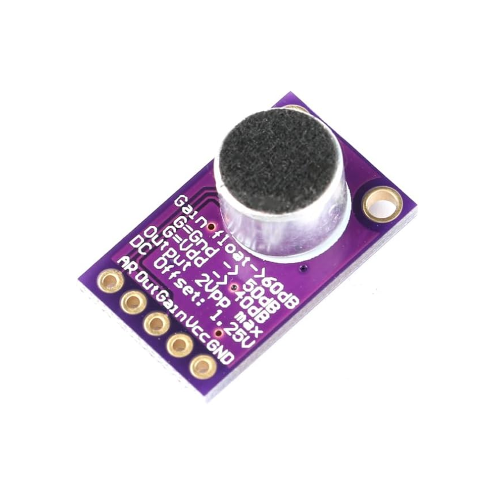
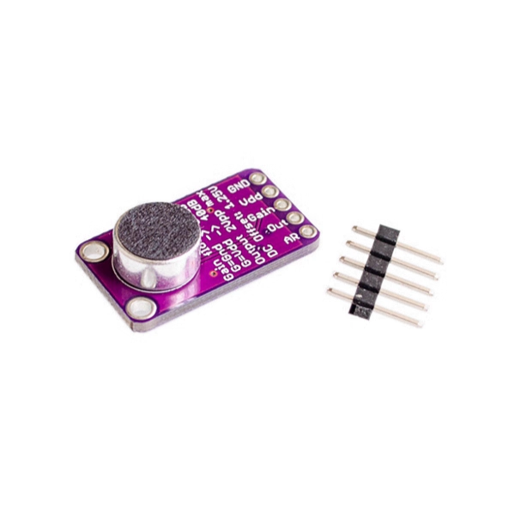
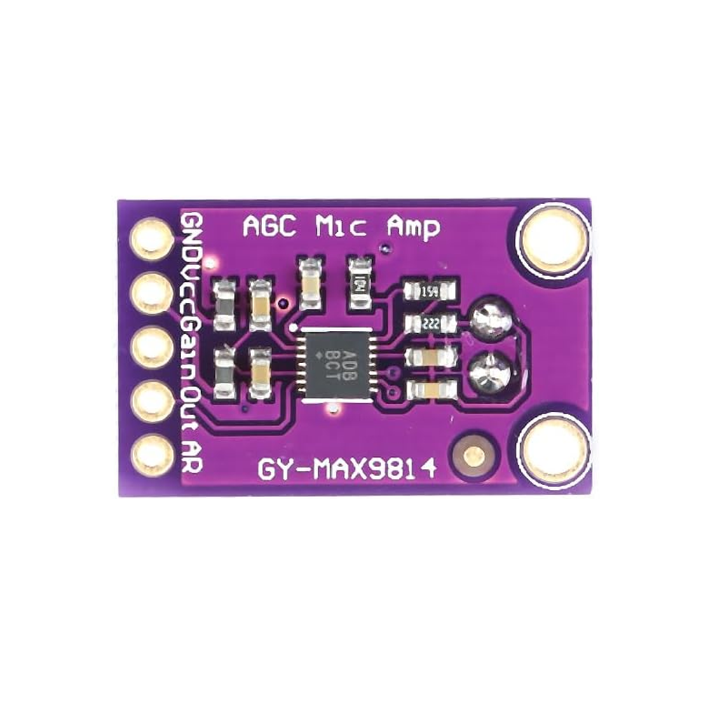
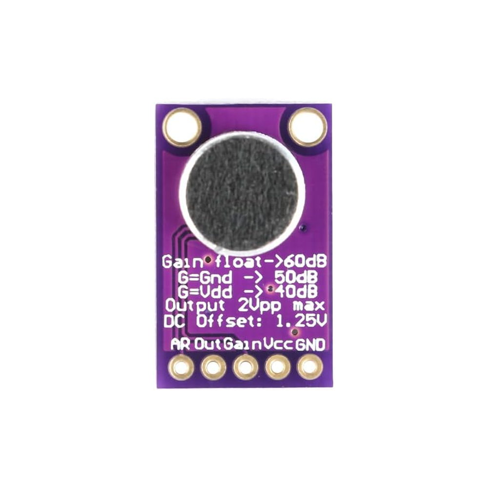
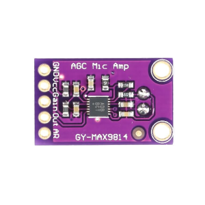
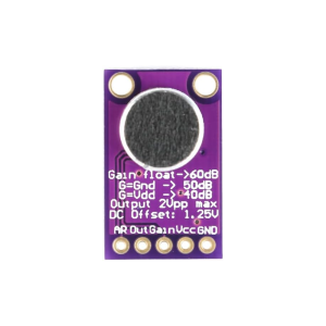
The MAX9814 High-Performance Microphone Amplifier Module is a compact, professional-grade audio preamplifier board designed for Arduino, Raspberry Pi, ESP32, and other microcontroller projects. Built around the MAX9814 IC from Maxim Integrated (now Analog Devices), this module features Automatic Gain Control (AGC) and a built-in electret microphone, delivering clean, consistent audio amplification across a wide range of sound levels. It is an ideal solution for sound level meters, voice recording, clap detection, audio spectrum analyzers, and audio-reactive projects.
At the heart of the module is the MAX9814, a high-performance microphone amplifier with programmable gain, automatic gain control, and a low-noise bias voltage generator for the electret microphone. The AGC function automatically adjusts the amplification level based on the input signal strength — when the sound is quiet, the gain increases; when the sound is loud, the gain decreases. This ensures that the output signal remains within a usable range without clipping or distortion, making the module far more forgiving than fixed-gain amplifiers like the MAX4466.
The MAX9814 offers three selectable gain settings — 40dB, 50dB, and 60dB — configurable via the GAIN pin. Additionally, the Attack/Release Ratio can be set to 1:4000, 1:2000, or 1:500 via the A/R pin, allowing you to fine-tune the AGC response for different applications. The Attack Time is fixed at 30µs, while the Release Time varies based on the A/R setting. The AGC Threshold is internally set to 1.25V, with a hold time of 2.5ms to prevent rapid gain fluctuations.
The module outputs an analog voltage on the OUT pin that follows the audio waveform, centered at approximately VCC/2. This output connects directly to your microcontroller’s ADC pin, allowing you to sample the audio in real time. The low output noise (typically 40µV) and high PSRR make the module suitable for sensitive audio applications.
The module operates from a 2.7V to 5.5V DC supply, making it compatible with both 3.3V and 5V microcontrollers. The compact form factor with mounting holes allows easy integration into custom enclosures, portable devices, and sound-reactive projects. The 4-pin interface (VCC, GND, OUT, GAIN) provides simple, straightforward wiring.
The MAX9814 Audio Amplifier Module is widely used in sound level meters, clap detectors, voice-activated projects, audio spectrum analyzers, noise monitoring systems, interactive art installations, and educational STEM projects. It is also popular in DIY electronics and maker projects where clean, automatic audio amplification is required.
Important Note: The MAX9814 amplifies the audio waveform, not just the sound level. The output is an analog signal that follows the audio waveform, so your microcontroller must sample it fast enough (typically 1kHz–10kHz) to capture the signal accurately. The AGC function makes the module ideal for environments with varying sound levels, but for precise absolute sound level measurement, a fixed-gain amplifier like the MAX4466 may be preferred. The module is not waterproof and should be kept dry.
Whether you are building a sound level meter, a voice recorder, or an audio-reactive LED display, the MAX9814 Audio Amplifier Module provides a reliable, professional-grade solution with automatic gain control. It is suitable for individual makers, students, and businesses purchasing in bulk for product development or educational programs.
Features
-
MAX9814 microphone amplifier IC — High-performance with automatic gain control (AGC)
-
Built-in electret microphone — Captures ambient sound accurately
-
Automatic Gain Control (AGC) — Adjusts gain automatically based on sound level
-
Selectable gain — 40dB, 50dB, or 60dB via GAIN pin
-
Selectable Attack/Release ratio — 1:4000, 1:2000, or 1:500 via A/R pin
-
Low output noise — Typically 40µV for clean audio
-
Analog output — Direct connection to microcontroller ADC pins
-
Wide voltage range — 2.7V to 5.5V DC, compatible with 3.3V and 5V systems
-
Compact form factor — With mounting holes for easy integration
-
Wide application range — Sound level meters, clap detectors, voice recording, audio visualization
Technical Specifications
| # | Parameter | Specification |
|---|---|---|
| 1 | Module Type | Microphone amplifier with AGC |
| 2 | Amplifier IC | MAX9814 |
| 3 | Sensor Type | Electret condenser microphone |
| 4 | Operating Voltage | 2.7V – 5.5V DC |
| 5 | Gain Settings | 40dB / 50dB / 60dB (selectable) |
| 6 | Output Type | Analog (audio waveform) |
| 7 | Output Noise | 40µV typical |
| 8 | Pin Count | 4 pins (VCC, GND, OUT, GAIN) |