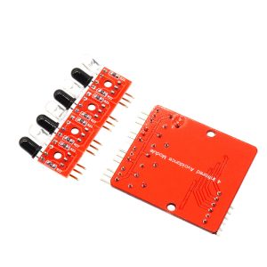
4-Way infrared tracking module

SKU: FA3008
Sensor Type

Infrared reflective (IR LED + phototransistor)

Number of Channels

4 independent channels

Operating Voltage

3.3V – 5V DC

Output Type

Digital (HIGH/LOW) per channel

Detection Height

5 – 15mm (recommended)

Sensitivity Adjustment

Potentiometer per channel

Indication

Power LED + 4 channel LEDs

Module Dimensions

Compact PCB with mounting holes

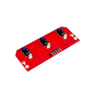
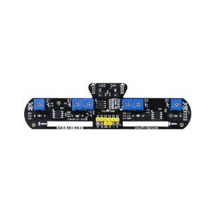
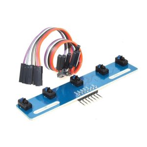
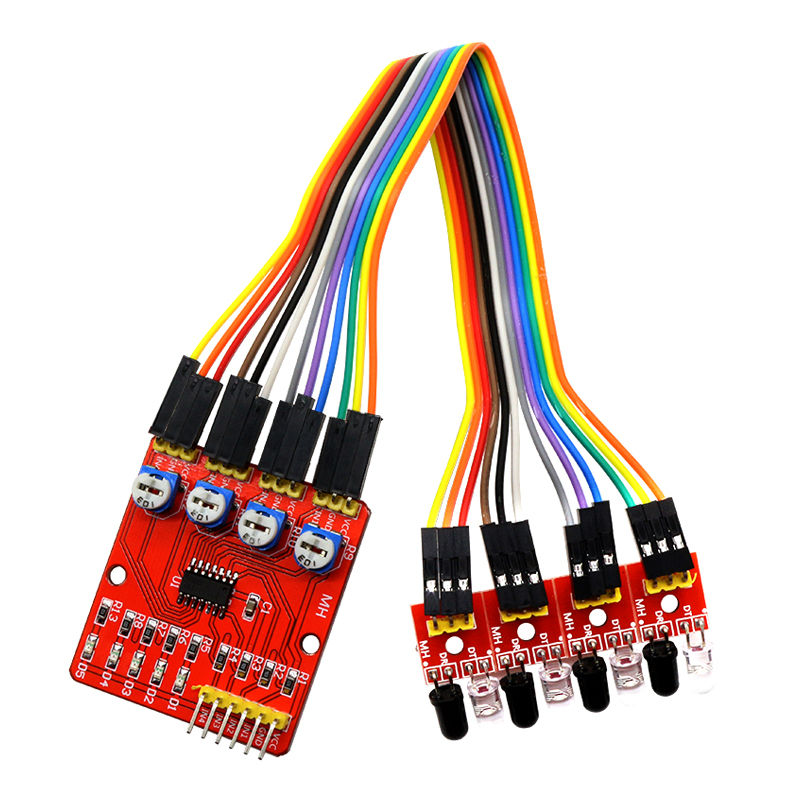
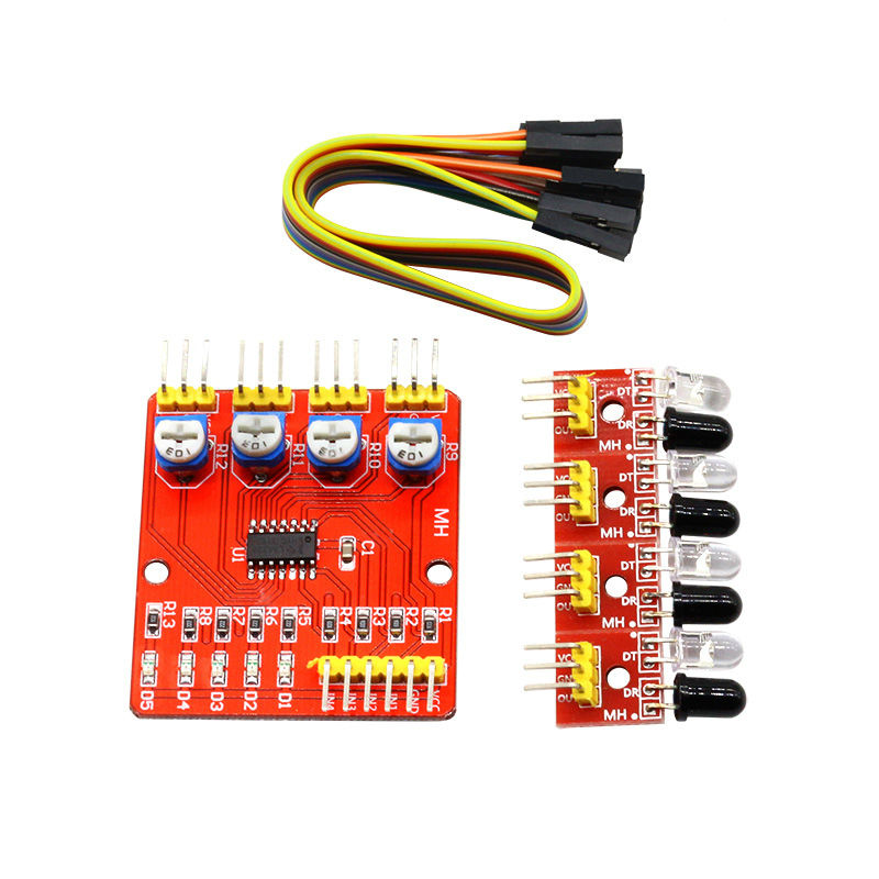
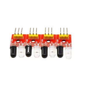
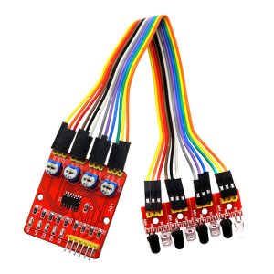
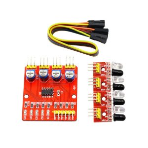
The 4-Way Infrared Tracking Module is a compact line-following sensor array designed for robotics, automation, and educational projects. It combines four independent infrared reflective sensors on a single board, each capable of detecting the presence or absence of a line beneath it. This makes it an ideal sensor suite for building line-following robots, automatic guided vehicles (AGVs), edge detection systems, and industrial sorting machines.

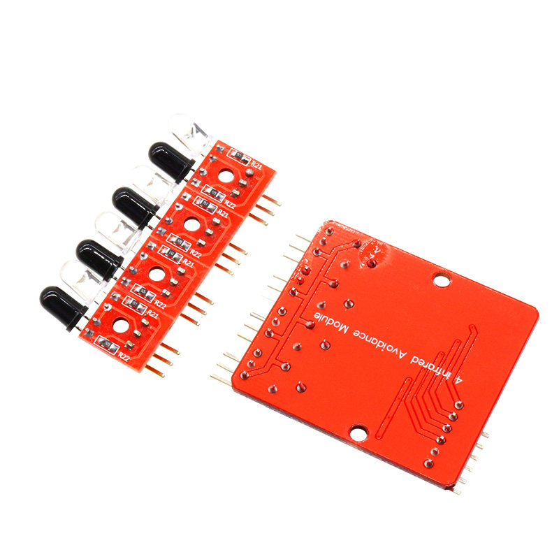
Each of the four sensor channels consists of an infrared emitter (IR LED) and an infrared receiver (phototransistor). The emitter emits infrared light downward toward the surface, and the receiver measures the reflected intensity. When the sensor is over a white surface (high reflectivity), the reflected IR is strong, and the output is typically LOW. When over a black line (low reflectivity), the reflected IR is weak, and the output is typically HIGH. This simple binary detection allows a robot to follow a black line on a white background (or vice versa).

The module features four independent digital outputs (OUT1, OUT2, OUT3, OUT4), one for each sensor channel. The outputs can be connected directly to a microcontroller’s digital input pins, enabling the robot to determine its position relative to the line and make steering decisions. The spacing between sensors (typically 10–11mm) provides a balance between detection resolution and physical size.

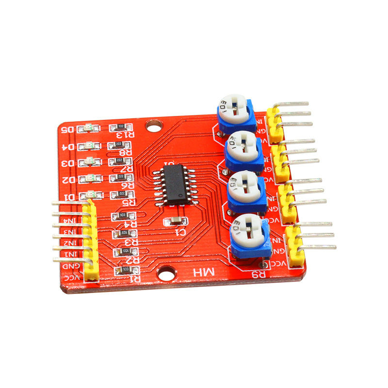
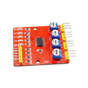
Each channel has an onboard potentiometer for adjusting detection sensitivity, allowing the module to adapt to different surface colors, lighting conditions, and line contrasts. A power indicator LED shows when the module is powered, and four channel indicator LEDs show the state of each sensor in real time.

The module operates from a 3.3V to 5V DC supply, making it compatible with Arduino, ESP32, STM32, Raspberry Pi, and other microcontrollers. The compact PCB design with mounting holes allows easy integration into robot chassis and custom enclosures. The module is widely used in line-following robots, maze-solving robots, obstacle avoidance systems, industrial automation, and educational STEM projects.

Important Note: The module is not waterproof and should be mounted 5–15mm above the surface for optimal detection. Detection performance can be affected by ambient infrared sources (such as sunlight or incandescent lighting) and highly reflective surfaces. For best results, use the module in controlled lighting conditions and calibrate the potentiometers for your specific surface.

Whether you are building a line-following robot, an automated sorting system, or a STEM educational kit, the 4-Way Infrared Tracking Module provides a reliable, affordable solution. It is suitable for individual makers, students, and businesses purchasing in bulk for product development or educational programs.

Features

  • Four independent IR sensor channels — Simultaneous detection across four positions

  • Digital outputs — Each channel provides a clean HIGH/LOW signal

  • Adjustable sensitivity — Onboard potentiometer for each channel

  • LED indicators — Power LED plus four channel status LEDs

  • Wide voltage range — 3.3V to 5V DC, compatible with Arduino, ESP32, STM32, Raspberry Pi

  • Compact PCB design — With mounting holes for easy integration

  • Simple interface — Four digital outputs for direct connection to MCU

  • Wide application range — Line-following robots, AGVs, edge detection, sorting machines

  • Proven technology — Widely used in educational and hobby robotics

  • Cost-effective — Affordable solution for line detection in volume production

Technical Specifications

# Parameter Specification
1 Sensor Type Infrared reflective (IR LED + phototransistor)
2 Number of Channels 4 independent channels
3 Operating Voltage 3.3V – 5V DC
4 Output Type Digital (HIGH/LOW) per channel
5 Detection Height 5 – 15mm (recommended)
6 Sensitivity Adjustment Potentiometer per channel
7 Indication Power LED + 4 channel LEDs
8 Module Dimensions Compact PCB with mounting holes


Usage

Getting Started

  1. Connect power — Supply 3.3V or 5V DC to the VCC pin and GND to ground. The power LED should light up.

  2. Connect outputs — Connect the four output pins (OUT1–OUT4) to digital input pins on your microcontroller:

    • Arduino: D2, D3, D4, D5

    • ESP32: Any available GPIO pins

  3. Mount the module — Position the module 5–15mm above the surface, with the sensors facing down. Ensure the module is perpendicular to the line for consistent detection.

  4. Adjust sensitivity — Place the module over a white area (or the background surface) and adjust each potentiometer until the corresponding LED just turns off. Then place it over the black line and verify the LED turns on.

  5. Upload and test — Write a simple sketch to read the four outputs and verify detection. The output state indicates whether each sensor is over the line or the background.

Output Logic

Surface Reflected IR Output State (Typical)
White (background) Strong reflection LOW (0V)
Black (line) Weak reflection HIGH (VCC)

(Note: Output logic may vary by module variant — verify with your specific module.)

Pin Connections

Module Pin Function
VCC Power (3.3V–5V)
GND Ground
OUT1 Sensor 1 digital output
OUT2 Sensor 2 digital output
OUT3 Sensor 3 digital output
OUT4 Sensor 4 digital output

Example Arduino Code

cpp
#define S1 2
#define S2 3
#define S3 4
#define S4 5

void setup() {
  Serial.begin(9600);
  pinMode(S1, INPUT);
  pinMode(S2, INPUT);
  pinMode(S3, INPUT);
  pinMode(S4, INPUT);
}

void loop() {
  Serial.print("S1: "); Serial.print(digitalRead(S1));
  Serial.print(" S2: "); Serial.print(digitalRead(S2));
  Serial.print(" S3: "); Serial.print(digitalRead(S3));
  Serial.print(" S4: "); Serial.println(digitalRead(S4));
  delay(100);
}

Typical Applications

  • Line-following robots — Detect and follow a black line on a white surface

  • Maze-solving robots — Navigate complex paths using line detection

  • Automated guided vehicles (AGVs) — Follow guide paths in industrial settings

  • Edge detection — Detect the edge of a surface or material

  • Sorting machines — Detect markings or labels on moving objects

  • Educational STEM projects — Teaching sensor principles and robotics

Notes for Business Buyers

  • Proven technology — Infrared reflective sensing is widely used in educational and hobby robotics.

  • Simple interface — Four digital outputs for easy integration with any microcontroller.

  • Adjustable sensitivity — Potentiometers allow adaptation to different surfaces and lighting conditions.

  • Suitable for bulk purchasing — Ideal for robotics kit manufacturers, educational institutions, and product development.

Q: What is the 4-Way Infrared Tracking Module used for?

It is a line-following sensor array for robotics, used in line-following robots, AGVs, edge detection, and automated sorting systems.

Q: How many sensor channels does the module have?

It has four independent infrared reflective sensor channels, each with its own digital output.

Q: What voltage does the module require?

It operates from 3.3V to 5V DC, making it compatible with Arduino, ESP32, STM32, and Raspberry Pi.

Q: How do I adjust the sensitivity?

Each channel has an onboard potentiometer. Place the module over the background surface and adjust until the LED just turns off, then verify detection over the line.

Q: What is the recommended mounting height?

Mount the module 5–15mm above the surface for optimal detection. Higher mounting may reduce detection reliability.

Q: What is the output logic?

Typically, the output is LOW over white surfaces (strong reflection) and HIGH over black lines (weak reflection). Verify with your specific module.

Q: Can I use this module outdoors?

Not recommended. Ambient infrared from sunlight can interfere with detection. Use in controlled lighting conditions for best results.

Q: Is the module waterproof?

No. The module is not waterproof and should be kept dry.

Q: How do I connect the module to an Arduino?

Connect VCC to 5V, GND to GND, and OUT1–OUT4 to digital pins D2–D5. Use digitalRead() to read each sensor.

Q: Can I purchase in bulk for a product development project?

Yes. This module is suitable for both individual users and business purchasing, including robotics kit manufacturers, educational institutions, and product development.