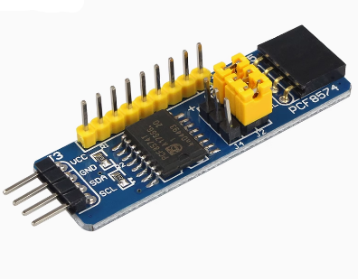
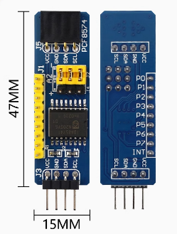
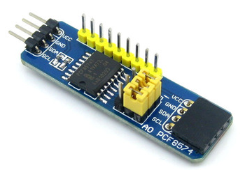
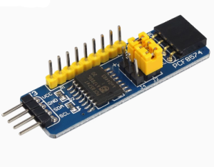
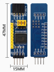
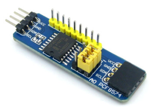
PCF8574 module PCF8574T module IO expansion module

SKU: FA2189
Expander Chip

PCF8574T

Interface

I2C (SDA, SCL)

I/O Pins

8 quasi-bidirectional

Voltage Range

2.5V – 6V

I2C Speed

100 kHz (standard), 400 kHz (fast)

Address Range

0x20 – 0x27 (configurable via A0–A2)

Pull-up Resistors

Onboard

Module Dimensions

Approx. 20 × 15 mm

The PCF8574 / PCF8574T IO Expansion Module is a compact, easy-to-use input/output expander that adds 8 additional GPIO pins to your microcontroller using only two I2C communication lines. Built around the PCF8574T chip from Texas Instruments, this module solves one of the most common problems in embedded projects — running out of available pins — by providing a simple, low-cost expansion solution.

At the heart of the module is the PCF8574T, an 8-bit I/O expander with an I2C interface. It provides 8 quasi-bidirectional I/O pins that can be independently configured as inputs or outputs. The chip communicates with the host microcontroller through the standard I2C bus (SDA and SCL), requiring only two pins for full control of all 8 expansion pins. This makes it ideal for projects where GPIO pins are scarce.

The module features onboard I2C pull-up resistors for reliable communication, and screw terminals or pin headers for easy connection to external devices. The compact PCB design with mounting holes makes it suitable for embedding into enclosures and custom projects. The 8 I/O pins are broken out with clear silkscreen labeling.

Address selection is handled through 3 onboard solder jumpers (A0, A1, A2) , allowing you to set the I2C address. This means you can connect up to 8 PCF8574 modules on the same I2C bus — providing a total of 64 additional I/O pins without conflicts. This scalability makes the module suitable for complex projects requiring many inputs or outputs.

The module operates from 2.5V to 6V, making it compatible with both 3.3V and 5V microcontrollers including Arduino, ESP32, ESP8266, STM32, and Raspberry Pi. The I2C bus supports standard mode (100 kHz) and fast mode (400 kHz) for responsive communication.

The PCF8574 is widely used in LCD displays (I2C backpacks), keypad matrix expansion, relay boards, LED indicators, sensor arrays, and industrial control panels. The module is supported by the Arduino Wire library and PCF8574 libraries (such as the one by Rob Tillaart or Renzo Mischianti), which provide simple functions for reading and writing pins.

Whether you are building a home automation system, a multi-sensor monitoring station, or a control panel with many buttons and LEDs, the PCF8574 IO Expansion Module provides a reliable, cost-effective way to add more I/O to your project. It is suitable for individual makers, students, and businesses purchasing in bulk for product development or educational programs.


Features

  • 8 additional GPIO pins — Expands your microcontroller‘s I/O using only two I2C lines

  • PCF8574T chip — Reliable, widely supported 8-bit I/O expander

  • I2C interface — Standard mode (100 kHz) and fast mode (400 kHz) support

  • Onboard pull-up resistors — For reliable I2C communication

  • Address selection jumpers — A0, A1, A2 allow up to 8 modules on the same bus

  • Wide voltage range — 2.5V to 6V, compatible with 3.3V and 5V systems

  • Compact form factor — Small PCB with mounting holes for easy integration

  • Clear labeling — Silkscreen markings for easy pin identification

  • Screw terminals or pin headers — Secure connections for external devices

  • Wide library support — Compatible with Arduino Wire and PCF8574 libraries


Technical Specifications 

# Parameter Specification
1 Expander Chip PCF8574T
2 Interface I2C (SDA, SCL)
3 I/O Pins 8 quasi-bidirectional
4 Voltage Range 2.5V – 6V
5 I2C Speed 100 kHz (standard), 400 kHz (fast)
6 Address Range 0x20 – 0x27 (configurable via A0–A2)
7 Pull-up Resistors Onboard
8 Module Dimensions Approx. 20 × 15 mm

Usage

Getting Started

  1. Connect power — Supply 3.3V or 5V to the VCC pin and GND to ground.

  2. Connect I2C lines — Connect SDA and SCL to your microcontroller‘s I2C bus.

    • Arduino Uno: SDA → A4, SCL → A5

    • ESP32: SDA → GPIO21, SCL → GPIO22 (default)

    • ESP8266: SDA → D2, SCL → D1

  3. Set the I2C address — Solder the A0, A1, A2 jumpers to set the module‘s I2C address. The default address is typically 0x20 (all jumpers open).

  4. Install the library — Install the PCF8574 library by Renzo Mischianti or Rob Tillaart through the Arduino Library Manager.

  5. Write your code — Use the library functions to set pin modes and read/write pin states.

Address Configuration

A0 A1 A2 I2C Address
Open Open Open 0x20
Closed Open Open 0x21
Open Closed Open 0x22
Closed Closed Open 0x23
Open Open Closed 0x24
Closed Open Closed 0x25
Open Closed Closed 0x26
Closed Closed Closed 0x27

Example Arduino Code

cpp
#include <Wire.h>
#include <PCF8574.h>

PCF8574 pcf8574(0x20);  // Default address 0x20

void setup() {
  Serial.begin(9600);
  pcf8574.begin();
  pcf8574.pinMode(P0, OUTPUT);  // Set P0 as output
  pcf8574.pinMode(P1, INPUT);   // Set P1 as input
}

void loop() {
  pcf8574.digitalWrite(P0, HIGH);  // Turn on P0
  delay(500);
  pcf8574.digitalWrite(P0, LOW);   // Turn off P0
  delay(500);
  Serial.println(pcf8574.digitalRead(P1));  // Read P1 state
}

Typical Applications

  • LCD display backpacks — Control 16×2 LCDs with only two I2C pins

  • Keypad matrix expansion — Scan multiple buttons with fewer MCU pins

  • Relay boards — Control multiple relays through I2C

  • LED indicators — Drive multiple status LEDs

  • Sensor arrays — Read multiple digital sensors

  • Industrial control panels — Expand I/O for equipment control

Notes for Business Buyers

  • Scalable — Up to 8 modules on one I2C bus provide 64 additional I/O pins.

  • Wide compatibility — Works with 3.3V and 5V systems.

  • Proven technology — PCF8574 is a widely adopted I/O expander with extensive documentation.

  • Suitable for bulk purchasing — Ideal for product development, educational kits, and commercial deployments.

Q: What is the PCF8574 IO Expansion Module used for?

It adds 8 additional GPIO pins to your microcontroller using only two I2C communication lines, solving pin shortage problems in embedded projects.

Q: How many modules can I connect to the same I2C bus?

Up to 8 modules can be connected on the same I2C bus using different addresses, providing a total of 64 additional I/O pins.

Q: How do I set the I2C address?

Use the A0, A1, A2 solder jumpers on the module. Solder or leave open the jumpers to select one of 8 possible addresses (0x20–0x27).

Q: What is the default I2C address?

The default address is typically 0x20 when all address jumpers are left open.

Q: What voltage does the module require?

It operates from 2.5V to 6V, making it compatible with both 3.3V and 5V systems.

Q: What library should I use?

Use the PCF8574 library by Renzo Mischianti or Rob Tillaart, available through the Arduino Library Manager.

Q: Can I use this module with an ESP32?

Yes. Connect SDA to GPIO21 and SCL to GPIO22 (default I2C pins), and use the same library.

Q: Are the I/O pins bidirectional?

Yes. Each of the 8 pins can be independently configured as an input or output using the library.

Q: Does the module have pull-up resistors?

Yes. The module includes onboard I2C pull-up resistors for reliable communication.

Q: Can I purchase in bulk for a school or company?

Yes. This module is suitable for both individual users and business purchasing, including product development, educational kits, and commercial deployments.