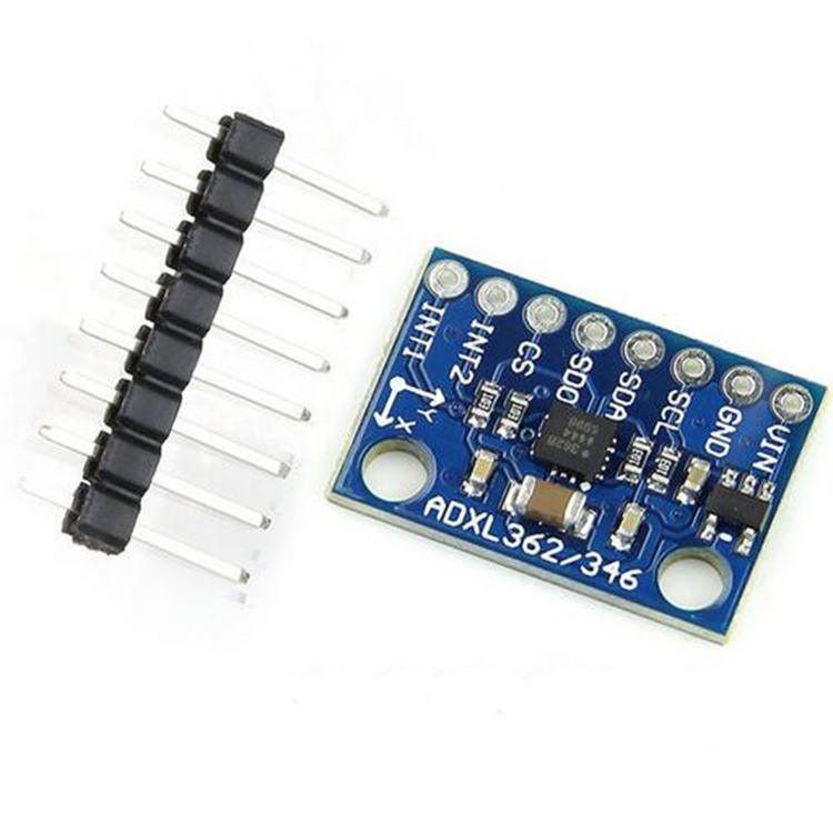
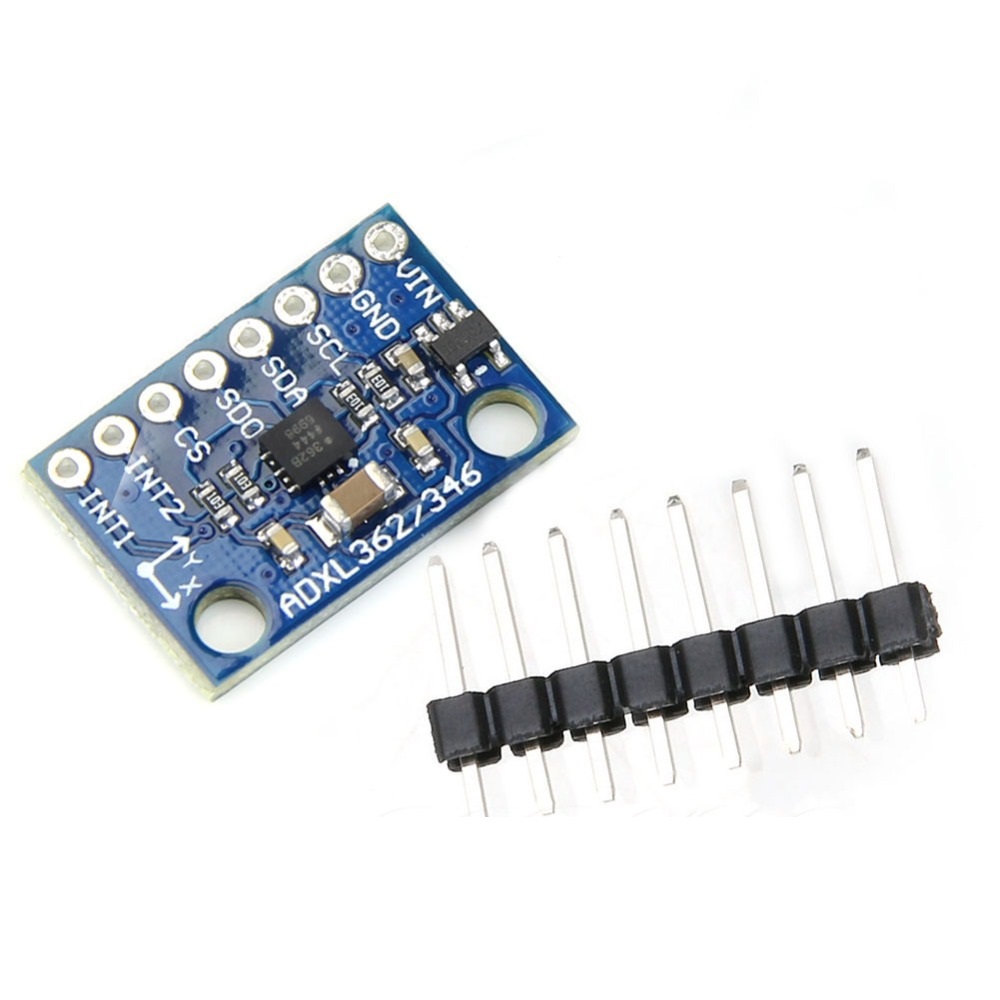
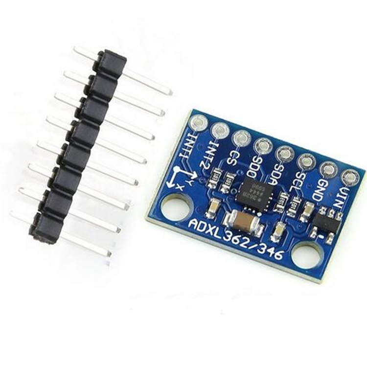
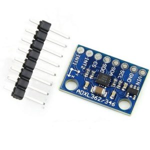
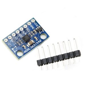
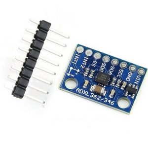
GY-362 ADXL362 3-Axis Digital Accelerometer Module – SPI Interface, Low Power, High Resolution

SKU: FA2184
Sensor Chip

Analog Devices ADXL362

Axes

3-axis (X, Y, Z)

ADC Resolution

12-bit (8-bit mode available)

Measurement Range

±2 g / ±4 g / ±8 g (user selectable)

Resolution

1 mg/LSB on ±2 g range

Interface

SPI (4-wire)

Supply Voltage

1.6 V – 3.5 V

Current Consumption

1.8 µA @ 100 Hz ODR; 270 nA wake-up mode

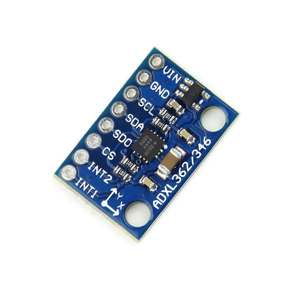
The GY-362 ADXL362 is a breakout module built around the Analog Devices ADXL362 ultralow-power 3-axis MEMS accelerometer. It is designed for applications where battery life is critical — the sensor consumes less than 2 µA at a 100 Hz output data rate and just 270 nA in motion-triggered wake-up mode, allowing it to run for years on a coin cell battery .

Unlike accelerometers that achieve low power through duty-cycling (which causes signal aliasing), the ADXL362 samples the full bandwidth of the sensor at all data rates without undersampling . It always provides 12-bit output resolution (with an optional 8-bit mode for efficient single-byte transfers), and offers user-selectable measurement ranges of ±2 g, ±4 g, and ±8 g, with a resolution of 1 mg/LSB on the ±2 g range .

The module communicates via a SPI digital interface, with a CS pin for chip-select and INT1/INT2 pins for interrupt output . An on-chip temperature sensor is included, accurate to approximately ±0.5°C after calibration . The sensor also includes a built-in FIFO buffer and motion-activated wake-up functionality, which can autonomously wake up a host microcontroller or directly control an external switch via a pin output — enabling true system-level power savings .

The GY-362 module breaks out the ADXL362 onto a compact PCB with a standard pin header for easy connection to breadboards and jumper wires. It operates from a wide 1.6 V to 3.5 V supply range, making it compatible with 1.8 V and 3.3 V logic systems .

Compatibility Note: The ADXL362 is not pin-compatible or software-compatible with the popular ADXL345. It uses a different SPI command structure and register map. You must use a dedicated ADXL362 library, such as the one by Anne Mahaffey (available on GitHub) or the ADXL362DMA library by rickkas7 .

Typical applications include hearing aids, home healthcare devices, motion-enabled power-save switches, wireless sensors, and motion-enabled metering devices .


Features

  • Ultralow power consumption — <2 µA at 100 Hz ODR, 270 nA in wake-up mode, 10 nA standby

  • 12-bit output resolution — Always provides 12-bit data; 8-bit mode available for efficient transfers

  • Selectable measurement ranges — ±2 g, ±4 g, ±8 g via SPI command

  • SPI digital interface — 4-wire SPI with CS, SCK, MOSI, MISO

  • Motion-activated wake-up — Autonomous interrupt processing without MCU intervention

  • Built-in temperature sensor — On-chip 12-bit temperature sensor

  • Deep FIFO buffer — Reduces host processor load

  • Wide supply range — 1.6 V to 3.5 V operation

  • Self-test capability — Verifies mechanical and electronic systems

  • Compact module form factor — Standard pin header for breadboard use


Technical Specifications 

# Parameter Specification
1 Sensor Chip Analog Devices ADXL362
2 Axes 3-axis (X, Y, Z)
3 ADC Resolution 12-bit (8-bit mode available)
4 Measurement Range ±2 g / ±4 g / ±8 g (user selectable)
5 Resolution 1 mg/LSB on ±2 g range
6 Interface SPI (4-wire)
7 Supply Voltage 1.6 V – 3.5 V
8 Current Consumption 1.8 µA @ 100 Hz ODR; 270 nA wake-up mode

Usage

Getting Started

  1. Connect power — Supply 3.3V to the VCC pin and GND to ground. The ADXL362 operates from 1.6V to 3.5V .

  2. Connect SPI lines — Wire the module to your microcontroller’s SPI bus:

    • CS → Any digital pin (chip select)

    • SCK → SPI clock

    • MOSI → SPI data out (from MCU)

    • MISO → SPI data in (to MCU)

    • INT1/INT2 → Optional interrupt pins

  3. Install the library — Install the ADXL362 library by Anne Mahaffey or the ADXL362DMA library by rickkas7 .

  4. Verify communication — Run a basic read example to confirm the sensor responds. The library includes a readXYZData function that returns X, Y, Z, and temperature values .

  5. Configure the sensor — Set the measurement range, output data rate, and activity/inactivity thresholds for wake-up functionality .

Pin Connections (Arduino Example)

Module Pin Arduino Uno ESP32
VCC 3.3V 3.3V
GND GND GND
CS D10 Any GPIO
SCK D13 GPIO18
MOSI D11 GPIO23
MISO D12 GPIO19
INT1 D2 (optional) Any GPIO

Example Arduino Code (Basic Read)

cpp
#include <SPI.h>
#include <ADXL362.h>

ADXL362 accel;
int x, y, z, temp;

void setup() {
  Serial.begin(9600);
  accel.begin(10);           // CS on pin 10
  accel.beginMeasure();      // Start measurement mode
}

void loop() {
  accel.readXYZData(x, y, z, temp);
  Serial.print("X="); Serial.print(x);
  Serial.print(" Y="); Serial.print(y);
  Serial.print(" Z="); Serial.print(z);
  Serial.print(" Temp="); Serial.println(temp);
  delay(500);
}

Motion-Activated Wake-Up

The ADXL362 can wake up a sleeping Arduino when motion is detected. Configure the activity/inactivity thresholds and connect INT1 to an Arduino interrupt pin (e.g., D2). When motion exceeds the threshold, the sensor asserts INT1, waking the MCU. The MCU can then read acceleration data and return to sleep when motion stops .

Typical Applications

  • Hearing aids — Motion detection for power saving

  • Home healthcare devices — Patient activity monitoring

  • Motion-enabled power save switches — Wake on movement

  • Wireless sensors — Battery-powered remote monitoring

  • Motion-enabled metering — Tamper detection and activity logging

  • Wearable devices — Step counting and activity tracking

Q: What is the GY-362 ADXL362 module used for?

It is an ultralow-power 3-axis accelerometer module for battery-powered motion sensing applications, including wearables, wireless sensors, and motion-activated switches .

Q: Is the ADXL362 compatible with ADXL345 libraries?

No. The ADXL362 uses a different SPI command structure and register map than the ADXL345. You must use a dedicated ADXL362 library such as the one by Anne Mahaffey .

Q: What is the power consumption of the ADXL362?

Less than 2 µA at 100 Hz ODR, 270 nA in motion-triggered wake-up mode, and 10 nA in standby .

Q: What measurement ranges does the ADXL362 support?

It supports ±2 g, ±4 g, and ±8 g, selectable via SPI command .

Q: What is the resolution of the ADXL362?

It provides 12-bit output resolution, with 1 mg/LSB on the ±2 g range .

Q: What interface does the module use?

It uses a 4-wire SPI interface (CS, SCK, MOSI, MISO) .

Q: Does the ADXL362 have a temperature sensor?

Yes. It includes an on-chip 12-bit temperature sensor .

Q: Can the ADXL362 wake up a sleeping microcontroller?

Yes. The sensor supports motion-activated wake-up and can assert an interrupt pin (INT1 or INT2) when activity is detected, waking a sleeping MCU .

Q: What is the supply voltage range?

The ADXL362 operates from 1.6 V to 3.5 V .

Q: Can I purchase in bulk for a product development project?

Yes. This module is suitable for both individual users and business purchasing, including wearable product development, battery-powered sensor nodes, and commercial deployments.