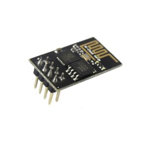
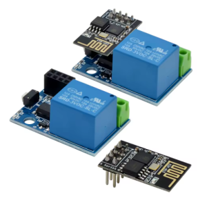
WiFi Smart Relay Module with ESP-01S – Wireless IoT Power Switch for Home Automation

SKU: FA2180-1
Compatible Module

ESP-01S (8-pin socket)

Relay Output

High-current relay with NO/NC/COM terminals

Input Voltage

Wide DC input with onboard regulator

ESP-01S Supply

3.3V regulated

Wireless Standard

WiFi 802.11 b/g/n (via ESP-01S)

Flash Memory

4MB (ESP-01S)

Control Interface

WiFi (standalone)

Terminal Type

Screw terminals for power and relay contacts

The WiFi Smart Relay Module with ESP-01S is a compact, ready-to-use IoT power switch designed to add wireless control to home appliances, lighting, and other electrical devices. It combines the popular ESP-01S WiFi module with a high-current relay output, providing a simple path to internet-connected switching without the need for a separate microcontroller.

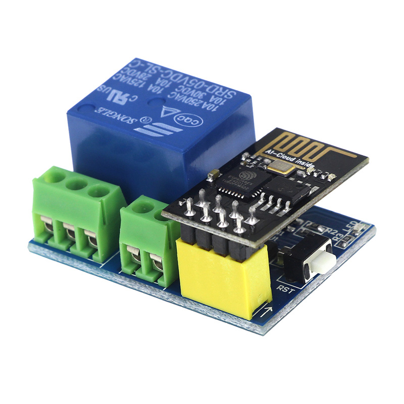
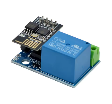
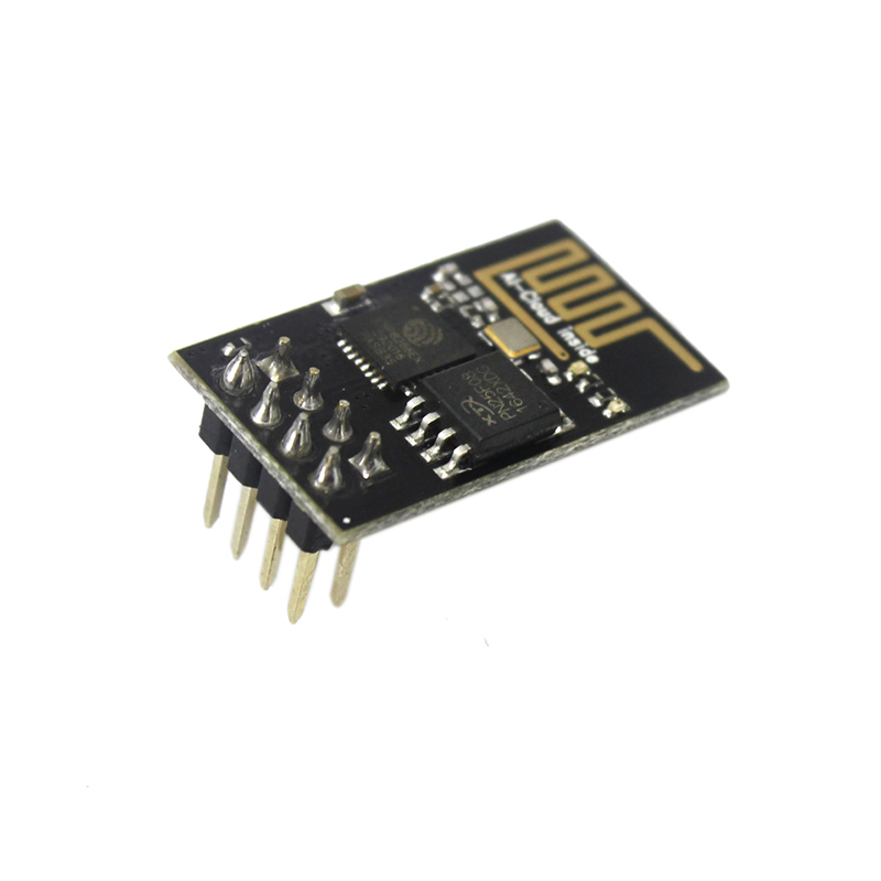
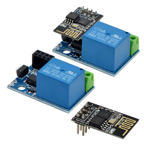
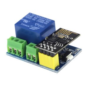
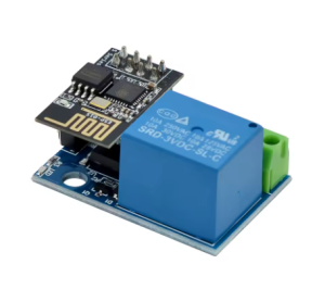
The module features an onboard socket for the ESP-01S WiFi module, which handles all wireless connectivity and logic control. The ESP-01S connects to your WiFi network and can be controlled through a web browser, mobile app, or cloud platform. The module also includes an onboard voltage regulator that provides the required 3.3V to the ESP-01S from a wide input voltage range, simplifying power supply design.

The relay output is rated for high-current switching, suitable for controlling AC or DC loads depending on the relay variant. Screw terminals provide secure connections for the relay’s normally-open (NO), normally-closed (NC), and common (COM) contacts, as well as the power input. This makes the board directly compatible with household wiring for lighting and appliance control.

The module is designed for standalone operation, meaning once the ESP-01S is programmed and inserted, the module can operate independently without a separate microcontroller. The ESP-01S handles WiFi connectivity, logic, and relay control, making this a complete IoT switching solution in a compact package.

Typical applications include smart home lighting control, remote appliance switching, wireless sensor-triggered automation, and IoT prototyping. The module is compatible with popular firmware including ESP8266 AT commands, NodeMCU, MicroPython, and Arduino core for ESP8266, giving you flexibility in how you develop and deploy your project.

The ESP-01S module features 4MB flash and WiFi 802.11 b/g/n connectivity, providing reliable wireless performance for IoT applications. The module supports station mode, soft-AP mode, and station+AP mode, allowing flexible network configurations.

Whether you are a maker building your first smart home device, a student learning IoT concepts, or a business purchasing in bulk for product development, the WiFi Smart Relay Module with ESP-01S offers a practical, cost-effective foundation.


Features

  • Onboard ESP-01S socket — Easy module insertion, replacement, and separate firmware flashing

  • High-current relay output — Controls AC or DC loads with NO/NC/COM screw terminals

  • Onboard voltage regulator — Provides stable 3.3V to the ESP-01S from a wide input range

  • Standalone operation — No separate microcontroller required; the ESP-01S handles WiFi and logic

  • Screw terminal connections — Secure wiring for power, relay contacts, and load

  • Compact form factor — Small footprint suitable for embedding into enclosures and junction boxes

  • Wide firmware compatibility — Supports AT commands, NodeMCU, MicroPython, and Arduino core

  • DIY and OEM friendly — Ideal for custom smart home and IoT product development


Technical Specifications 

# Parameter Specification
1 Compatible Module ESP-01S (8-pin socket)
2 Relay Output High-current relay with NO/NC/COM terminals
3 Input Voltage Wide DC input with onboard regulator
4 ESP-01S Supply 3.3V regulated
5 Wireless Standard WiFi 802.11 b/g/n (via ESP-01S)
6 Flash Memory 4MB (ESP-01S)
7 Control Interface WiFi (standalone)
8 Terminal Type Screw terminals for power and relay contacts

Usage

Getting Started

  1. Flash the ESP-01S (if needed) — Use a USB-to-serial adapter to program the ESP-01S with your desired firmware before inserting it into the socket. Connect the adapter to the ESP-01S’s TX, RX, VCC (3.3V), and GND pins.

  2. Insert the ESP-01S — Align the ESP-01S’s pins with the onboard 8-pin socket and press firmly to seat. Note the orientation; the antenna should face outward.

  3. Power the module — Connect a suitable DC supply to the power input terminals. The onboard regulator powers the ESP-01S.

  4. Connect the load — Wire the device you want to control to the relay’s NO or NC contacts and COM terminal. Observe the markings for proper connection.

  5. Test the circuit — Power on the module. The ESP-01S should boot and connect to your WiFi network (if configured). Trigger the relay through your chosen control method.

Typical Control Methods

  • Web server — Program the ESP-01S to host a simple web page with on/off buttons.

  • MQTT — Connect to an MQTT broker for integration with home automation platforms.

  • AT commands — Control the relay through serial AT commands from another device.

  • Smart home platforms — Integrate with compatible home automation systems.

Typical Applications

  • Smart home lighting — Remote control of lamps and ceiling lights via WiFi.

  • Appliance switching — Turn on/off fans, heaters, and other household devices.

  • Remote monitoring and control — Integrate with IoT platforms for remote access.

  • Sensor-triggered automation — Combine with sensors for automatic relay activation.

  • Educational projects — Teaching IoT concepts, WiFi communication, and relay control.

  • OEM product development — Customizable foundation for commercial smart switches.

Notes for Business Buyers

  • Socket-compatible design — Easy module replacement and separate firmware flashing reduce production and maintenance complexity.

  • Standalone operation — No additional microcontroller required, reducing BOM cost.

  • Wide firmware support — Flexible development options for different team skill sets.

  • Suitable for bulk purchasing — Ideal for smart home integrators, product developers, and educational institutions.

Q: Is the ESP-01S module included with this board?

Yes. This module includes the ESP-01S WiFi module with 4MB flash.

Q: What is the difference between ESP-01 and ESP-01S?

The ESP-01S is an improved version of the original ESP-01, with a different onboard LED configuration and more reliable boot behavior. Both fit the same 8-pin socket.

Q: How do I program the ESP-01S?

Use a USB-to-serial adapter (3.3V logic) connected to the ESP-01S’s TX, RX, VCC, and GND pins. You can program it before inserting it into the socket.

Q: What firmware can I run on the ESP-01S?

The ESP-01S supports AT commands, NodeMCU (Lua), MicroPython, and the Arduino core for ESP8266.

Q: How do I power the module?

Connect a suitable DC supply to the power input terminals. The onboard regulator provides 3.3V to the ESP-01S. Check the product label for the specific input voltage range.

Q: What is the maximum load the relay can switch?

The relay rating depends on the specific variant. Check the product label for the exact rating. For inductive loads, keep the load current below 60–70% of the rated value.

Q: Can I control AC devices with this module?

Yes, if the relay is rated for AC voltage. Important: Ensure proper isolation and safety precautions when working with mains voltage. If you are not experienced with AC wiring, consult a qualified professional.

Q: Does the module work without a separate microcontroller?

Yes. This is a standalone module. Once the ESP-01S is programmed and inserted, it handles WiFi connectivity, logic, and relay control independently.

Q: Can I use this module with home automation platforms?

Yes. By programming the ESP-01S with MQTT or HTTP protocols, you can integrate it with popular home automation platforms.

Q: Can I purchase in bulk for a school or company?

Yes. This module is suitable for both individual users and business purchasing, including smart home integrators, product developers, and educational institutions.