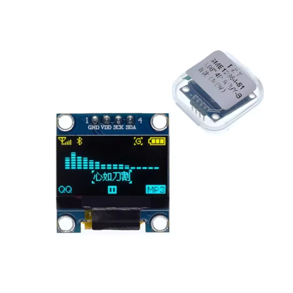
0.96″ Inch Yellow+Blue I2C IIC OLED LCD Module 4pin SSD1315 Chip 128*64 (GND VDD SCK SDA)

SKU: FA2125-3-0
Display Size

0.96 inch

Resolution

128 × 64 pixels

Driver IC

SSD1315

Display Color

Yellow + Blue (split-screen)

Interface

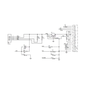
I2C (4-pin: GND, VDD, SCK, SDA)

Operating Voltage

3.3V – 5V

Operating Current

< 20mA typical

Module Dimensions

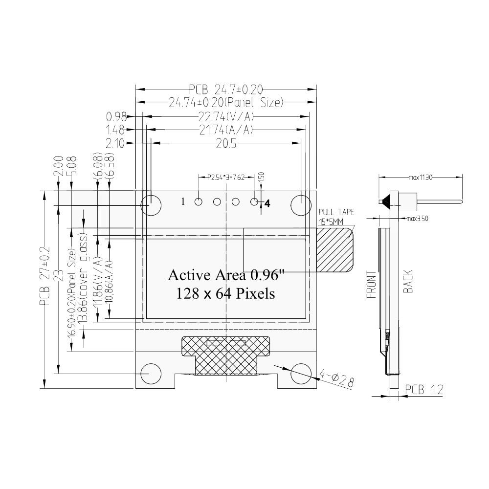
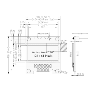
Approx. 27 × 27 mm

The 0.96″ Yellow+Blue I2C OLED LCD Module is a compact, dual-color display designed for microcontroller projects, embedded systems, and DIY electronics. It features a 128×64 pixel resolution with a distinctive yellow and blue split-screen layout — the top portion of the display shows yellow text or graphics, while the bottom portion shows blue. This two-tone design is particularly useful for separating different types of information, such as a yellow status header and blue data fields, or a yellow title area and blue content region.

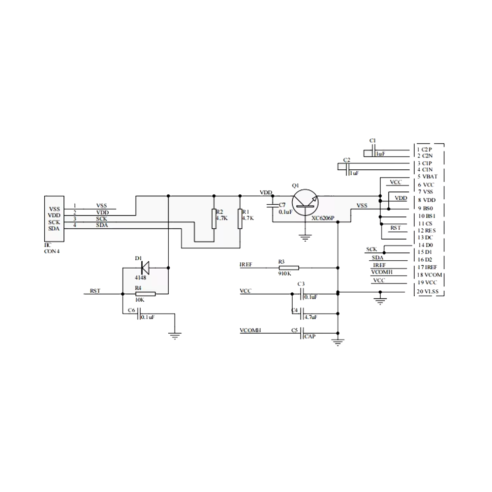
At the heart of the module is the SSD1315 driver chip, a modern, widely supported controller that offers excellent compatibility and performance. With its 4-pin I2C interface (GND, VDD, SCK, SDA), the module requires only two data lines to connect to your microcontroller, making it one of the simplest displays to integrate into any project.

OLED technology provides self-illuminating pixels — meaning each pixel emits its own light without a backlight — resulting in true blacks, infinite contrast ratio, and wide viewing angles. The yellow+blue color scheme provides visual distinction between screen regions and can be used to create more engaging user interfaces.

The I2C interface (also written as IIC) uses only two signal wires: SCK (serial clock) and SDA (serial data) , along with power (VDD) and ground (GND). This 4-pin design simplifies wiring and frees up microcontroller pins for other peripherals. The module supports standard I2C addresses (typically 0x3C or 0x3D).

The module operates from 3.3V to 5V logic levels, making it compatible with Arduino, ESP32, ESP8266, STM32, Raspberry Pi, and other popular platforms. It consumes very little power — typically less than 20mA during operation — making it suitable for battery-powered devices and portable electronics. The compact 27 × 27 mm form factor with mounting holes allows easy integration into custom enclosures and project panels.

Supported development environments include Arduino IDE (with the Adafruit_SSD1306 and U8g2 libraries), ESP-IDF, and MicroPython. The U8g2 library provides extensive font support, graphics primitives, and display control functions, making it easy to create professional-looking user interfaces.

Whether you are building a weather station, a digital clock, a sensor readout, a menu system, or a wearable device, the 0.96″ Yellow+Blue I2C OLED Module provides a reliable, visually distinctive display solution. It is suitable for individual makers, students, and businesses purchasing in bulk for product development or educational programs.


Features

  • 0.96-inch OLED display — 128×64 pixel resolution with yellow+blue split-screen output

  • Dual-color layout — Yellow top section and blue bottom section for visual information separation

  • SSD1315 driver chip — Modern, widely supported controller with excellent compatibility

  • 4-pin I2C interface — Only two data lines (SCK, SDA) plus power and ground

  • Self-illuminating OLED technology — True blacks, infinite contrast, wide viewing angles

  • 3.3V to 5V operation — Compatible with Arduino, ESP32, ESP8266, STM32, and Raspberry Pi

  • Low power consumption — Typically less than 20mA during operation

  • Compact form factor — 27 × 27 mm with mounting holes for easy integration

  • Wide library support — Compatible with Adafruit_SSD1306, U8g2, and other popular libraries

  • Multiple I2C addresses — Typically 0x3C or 0x3D, configurable via solder jumpers


Technical Specifications 

# Parameter Specification
1 Display Size 0.96 inch
2 Resolution 128 × 64 pixels
3 Driver IC SSD1315
4 Display Color Yellow + Blue (split-screen)
5 Interface I2C (4-pin: GND, VDD, SCK, SDA)
6 Operating Voltage 3.3V – 5V
7 Operating Current < 20mA typical
8 Module Dimensions Approx. 27 × 27 mm

Usage

Getting Started

  1. Connect power — Connect VDD to 3.3V or 5V and GND to ground.

  2. Connect I2C lines — Connect SCK to your microcontroller‘s I2C clock (SCL) and SDA to the I2C data line.

    • Arduino Uno: SCL → A5, SDA → A4

    • ESP32: SCL → GPIO22, SDA → GPIO21 (default)

    • ESP8266: SCL → D1, SDA → D2

  3. Install the library — Install the Adafruit_SSD1306 or U8g2 library through the Arduino Library Manager. You will also need the Adafruit_GFX library for graphics primitives.

  4. Find the I2C address — Run an I2C scanner sketch to confirm the display’s address (typically 0x3C).

  5. Upload a test sketch — Use a basic example to display text or graphics. The Adafruit_SSD1306 library includes a ssd1306_128x64_i2c example for testing.

Pin Connections

Module Pin Function Arduino Uno ESP32 ESP8266
GND Ground GND GND GND
VDD Power 5V or 3.3V 3.3V 3.3V
SCK I2C Clock A5 (SCL) GPIO22 D1
SDA I2C Data A4 (SDA) GPIO21 D2

Color Layout Notes

The yellow+blue display has two distinct regions:

  • Top section (yellow): Approximately the top 16 pixels of the 64-pixel height

  • Bottom section (blue): The remaining 48 pixels

When designing your UI, place headers, titles, or status indicators in the yellow region, and data fields, menus, or content in the blue region.

Typical Applications

  • Weather stations — Yellow header for location/time, blue data for temperature and humidity

  • Digital clocks — Yellow for time, blue for date and additional info

  • Sensor readouts — Yellow for sensor name, blue for readings

  • Menu systems — Yellow for menu title, blue for menu items

  • Wearable devices — Compact dual-color display for portable electronics

  • Instrument panels — Status displays with visual information hierarchy

Notes for Business Buyers

  • Visual distinction — Dual-color layout helps separate information types without complex graphics.

  • Low cost — Affordable display solution for volume production and educational kits.

  • Simple integration — 4-pin I2C interface reduces wiring complexity and microcontroller pin usage.

  • Suitable for bulk purchasing — Ideal for product development, educational programs, and commercial deployments.

Q: What is the 0.96" Yellow+Blue I2C OLED Module used for?

It is a compact dual-color display module for microcontroller projects, used for showing text, numbers, icons, and simple graphics with visual separation between screen regions.

Q: How is the yellow and blue color arranged on the display?

The display has a split-screen layout: the top portion is yellow (approximately 16 pixels) and the bottom portion is blue (approximately 48 pixels).

Q: What is the resolution of this display?

The display has a 128×64 pixel resolution.

Q: What driver chip does this module use?

It uses the SSD1315 driver chip, which is compatible with the SSD1306 in most libraries.

Q: How many pins does the module require?

It uses a 4-pin I2C interface: GND, VDD, SCK (SCL), and SDA.

Q: What is the I2C address of this display?

The default I2C address is typically 0x3C. Some modules may use 0x3D, which can be configured via a solder jumper on the back of the board.

Q: What voltage does the module require?

It operates from 3.3V to 5V, making it compatible with most microcontrollers.

Q: What library should I use?

Use the Adafruit_SSD1306 library with Adafruit_GFX, or the U8g2 library. Both are available through the Arduino Library Manager.

Q: Can I control the yellow and blue regions separately?

The color regions are fixed by the display hardware — the top pixels are always yellow and the bottom pixels are always blue. You control what is displayed in each region through your code.

Q: Can I purchase in bulk for a school or company?

Yes. This display module is suitable for both individual users and business purchasing, including classroom kits, product development, and commercial deployments.