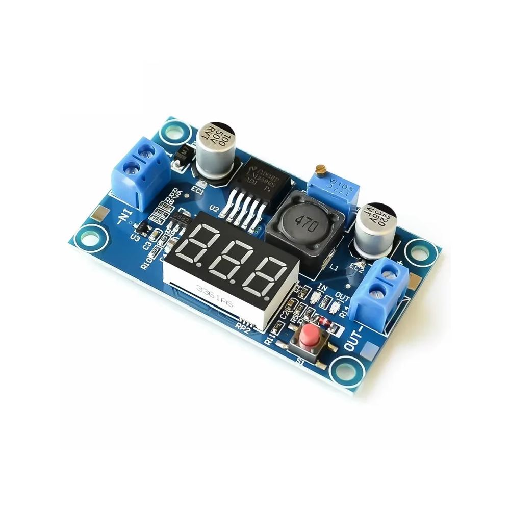
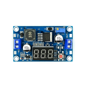
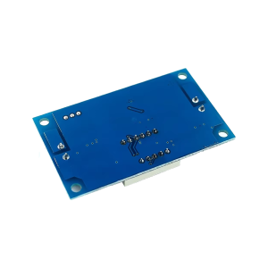
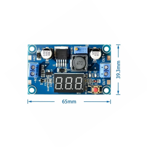
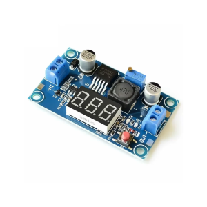
LM2596S DC-DC Buck Converter Reduced Voltage Regulator Power Module 36V 24V 12V to 5V 2A Voltage Stabilizer with Digital Voltmeter Display

SKU: FA2104-3
Converter IC

LM2596S

Input Voltage

4.5V – 40V DC

Output Voltage

1.25V – 37V DC (adjustable)

Maximum Output Current

2A continuous (3A peak)

Conversion Efficiency

Up to 92%

Switching Frequency

150 kHz

Display

Digital voltmeter (output voltage)

Board Dimensions

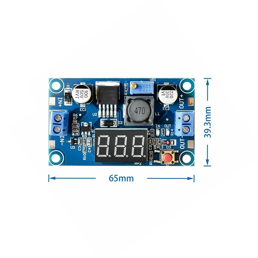
Approx. 66 × 36 × 14 mm

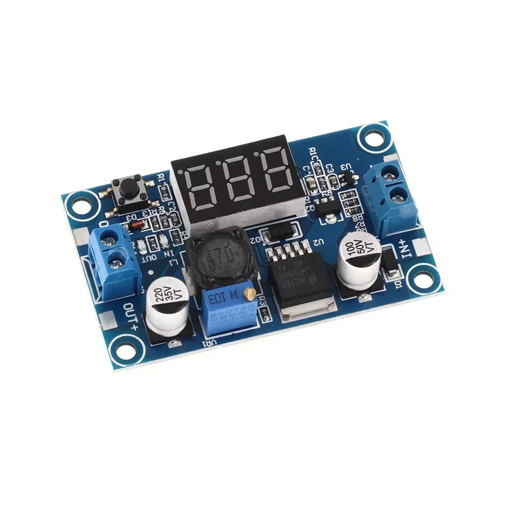
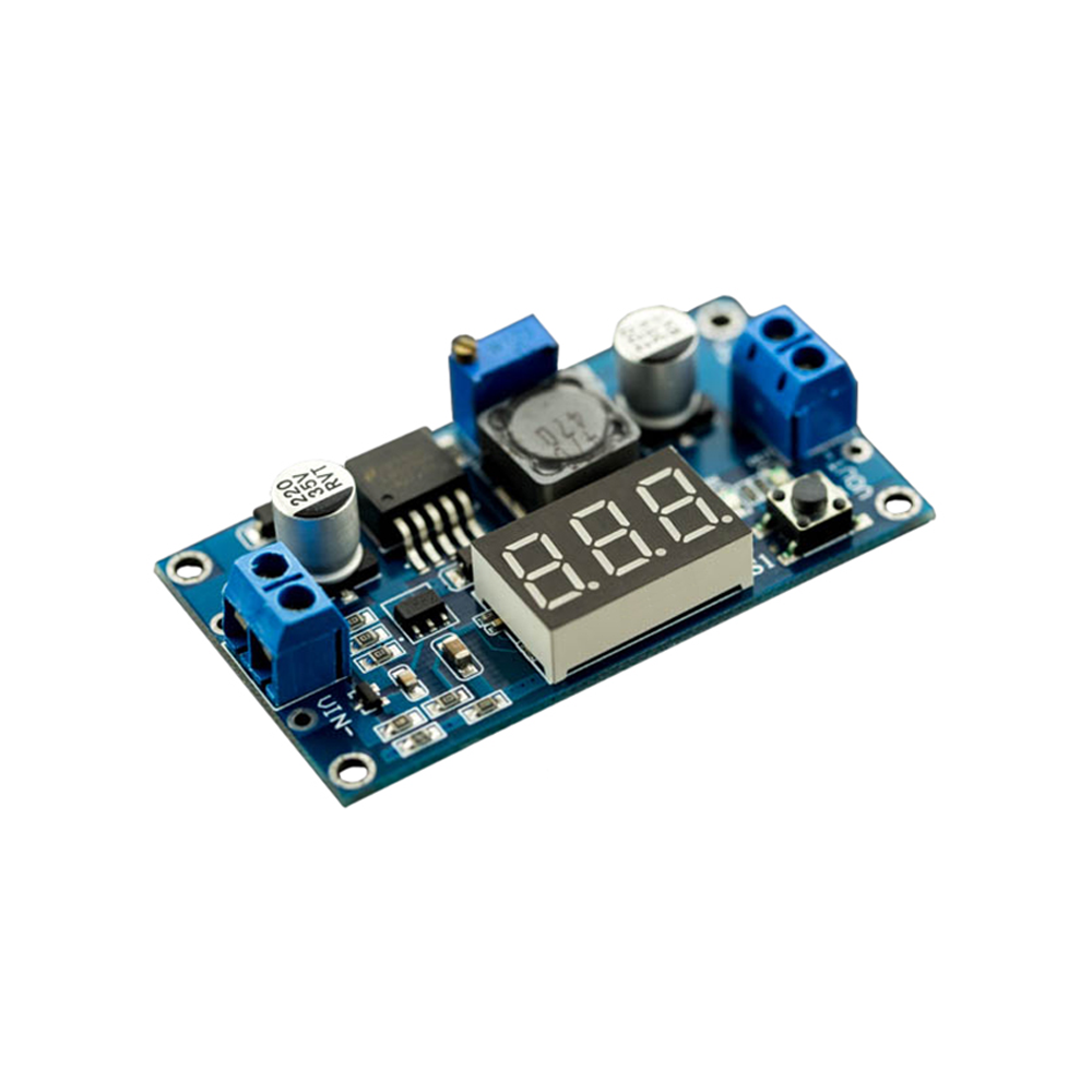
The LM2596S DC-DC Buck Converter Module is a compact, adjustable step-down voltage regulator designed to provide stable, reliable power for a wide range of electronic projects. Built around the LM2596S switching regulator IC, this module combines adjustable output voltage, 2A maximum output current, and an integrated digital voltmeter display — making it an ideal solution for DIY power supplies, battery charging, LED drivers, and embedded system power.

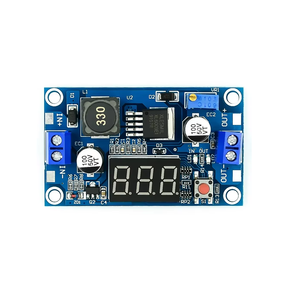
The module accepts an input voltage range of 4.5V to 40V DC and produces an adjustable output voltage from 1.25V to 37V DC. The output voltage is set using the onboard multi-turn potentiometer, allowing precise adjustment for your specific application. The module can deliver up to 2A of output current (3A peak with adequate cooling), making it capable of powering motors, LED arrays, and small embedded systems.

A standout feature of this module is the integrated digital voltmeter display, which shows the real-time output voltage. This eliminates the need for an external multimeter during setup and allows continuous monitoring of your power system. The display is powered directly from the module‘s output, so it activates whenever the module is powered.

At the heart of the module is the LM2596S buck (step-down) converter IC, which operates at a fixed switching frequency of 150 kHz. The conversion efficiency reaches up to 92%, minimizing power loss and heat generation. The module includes built-in protection circuits including over-current protection and thermal shutdown, ensuring safe and reliable operation.

The module features screw terminals for secure input and output wiring, and the compact PCB design with mounting holes makes it easy to integrate into custom enclosures and project boxes. The digital voltmeter adds convenience for bench testing, battery monitoring, and field diagnostics.

The LM2596S is widely used in bench power supplies, battery charging systems, LED drivers, solar power applications, and automotive electronics where a stable, lower voltage is needed from a higher supply.

Whether you are building a custom power supply, charging batteries, or designing an LED driver, the LM2596S Step-Down Module provides a reliable, efficient foundation with the added convenience of an integrated display. It is suitable for individual makers, students, and businesses purchasing in bulk for product development or educational programs.


Features

  • LM2596S buck converter IC — High-efficiency step-down regulator

  • Wide input voltage range — 4.5V to 40V DC input

  • Adjustable output voltage — 1.25V to 37V DC via onboard potentiometer

  • High output current — Up to 2A continuous (3A peak with cooling)

  • Integrated digital voltmeter — Real-time output voltage display

  • High conversion efficiency — Up to 92%

  • Fixed 150 kHz switching frequency — Compact design with smaller components

  • Built-in protection — Over-current protection and thermal shutdown

  • Screw terminals — Secure input and output wiring

  • Compact PCB with mounting holes — Easy integration into enclosures


Technical Specifications 

# Parameter Specification
1 Converter IC LM2596S
2 Input Voltage 4.5V – 40V DC
3 Output Voltage 1.25V – 37V DC (adjustable)
4 Maximum Output Current 2A continuous (3A peak)
5 Conversion Efficiency Up to 92%
6 Switching Frequency 150 kHz
7 Display Digital voltmeter (output voltage)
8 Board Dimensions Approx. 66 × 36 × 14 mm

Usage

Getting Started

  1. Connect input power — Connect your DC input source (4.5V–40V) to the IN+ and IN- terminals. Observe correct polarity.

  2. Connect the load — Connect your device or load to the OUT+ and OUT- terminals.

  3. Adjust output voltage — Using a small screwdriver, turn the onboard potentiometer while monitoring the digital voltmeter display. Set the desired output voltage before connecting sensitive loads.

  4. Power on and test — Apply input power and verify the output voltage on the display.

Important Notes

  • Input voltage must be higher than output voltage — This is a buck (step-down) converter. The input voltage must always be greater than the desired output voltage by at least 1.5V.

  • Output current limitation — The maximum continuous output current is 2A. For sustained high-current operation, add a heat sink to the LM2596S IC.

  • Heat dissipation — For high-power operation, ensure adequate ventilation or add a small heat sink.

  • Display accuracy — The onboard voltmeter provides convenient monitoring but may have slight tolerance (±0.1V typical). For critical applications, verify with a calibrated multimeter.

Typical Applications

  • Bench power supplies — Build adjustable power supplies with integrated voltage display

  • Battery charging — Charge lead-acid, lithium, and other batteries with adjustable voltage

  • LED drivers — Power LED arrays with precise voltage control

  • Solar power applications — Regulate solar panel output for battery charging or direct loads

  • Automotive electronics — Step down 12V or 24V vehicle power for sensitive devices

  • Embedded system power — Provide stable voltages for microcontrollers and sensors

Notes for Business Buyers

  • Integrated display — Eliminates need for external multimeters during setup and monitoring.

  • Cost-effective — Low unit cost makes it practical for volume production and educational programs.

  • Proven technology — LM2596S is a widely adopted buck converter with extensive documentation and community support.

  • Suitable for bulk purchasing — Ideal for product development, educational kits, and commercial deployments.

Q: What is the LM2596S Buck Converter Module used for?

It is a DC-DC step-down voltage regulator that reduces input voltage to a lower, adjustable output level. It is used in power supplies, battery chargers, LED drivers, and automotive electronics.

Q: What is the input and output voltage range?

Input: 4.5V to 40V DC. Output: 1.25V to 37V DC (adjustable).

Q: How do I adjust the output voltage?

Use a small screwdriver to turn the onboard potentiometer. Monitor the output on the digital voltmeter display to set the desired voltage.

Q: What is the maximum output current?

The module can deliver up to 2A continuous (3A peak with adequate cooling).

Q: What is the difference between LM2596 and LM2596S?

The LM2596S is a surface-mount version of the LM2596. Both offer similar performance, but the LM2596S is more commonly used in compact module designs.

Q: Is this a boost or buck converter?

This is a buck (step-down) converter. The input voltage must be higher than the output voltage.

Q: Does the module have protection features?

Yes. It includes over-current protection and thermal shutdown for safe operation.

Q: Can I use this module to charge a battery?

Yes. Set the output voltage to the battery‘s full charge voltage and connect the battery to the output terminals. For proper charging, additional charge control circuitry may be required for lithium batteries.

Q: What is the display accuracy?

The onboard voltmeter provides convenient monitoring with typical accuracy of ±0.1V. For critical applications, verify with a calibrated multimeter.

Q: Can I purchase in bulk for a product development project?

Yes. The LM2596S module is suitable for both individual users and business purchasing, including product development, educational programs, and commercial deployments.